background image


16 

                                  AP Profiles                                    

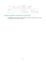
 State : I = Idle,   J = Join, JA = JoinAck,   IL = ImageLoad                    

         C = Config, R = Run,  KU = KeyUpdate, KC = KeyCfm                       

-------------------------------------------------------------------------------- 

 AP Name                          State Model              Serial-ID             

-------------------------------------------------------------------------------- 

ap1                               R/M   WA4620E-ACN        210235A1BUB139000435  

------------------------------------------------------------------------------- 

Verifying network connection for the fat AP 

Use the 

ping

 command on the fat AP to ping the uplink network device. If the ping operation succeeds, 

the AP is connected to the network successfully. 
 

Summary of Contents for WA4600 Series

Page 1: ...cting the AP to the power supply 14 Check before power on 14 Connecting PoE power supply 14 Connecting local power supply 15 Check after power on 15 Connecting the AP to the network 15 Verifying netwo...

Page 2: ...or access controllers ACs to provide wireless access for WLAN users All network settings are configured on the wireless switches or ACs The WA4600 AP can also operate as a fat AP to provide wireless a...

Page 3: ...1 dBi External antennas Power consumption 8 to 12 95 W 8 to 12 95 W Dimensions H W D 72 220 220 mm 2 83 8 66 8 66 in 72 220 220 mm 2 83 8 66 8 66 in Weight 1 5 kg 3 31 lb 1 4 kg 3 09 lb NOTE The WA46...

Page 4: ...ndition Take adequate safety measures to avoid injury and AP damage Make sure you place the AP in a dry and flat location and anti slip measures are in place Keep the AP clean and dust free Do not pla...

Page 5: ...Installation tools When installing the AP you may need the following tools Prepare these tools yourself Level Crimping pliers RJ 45 crimping pliers Wire stripping pliers Pincer pliers Percussion drill...

Page 6: ...rectly For more information about AP LEDs see Appendix LEDs and ports Verify that cabling on the installation site has been completed To ensure the PoE performance H3C recommends that you use GE inter...

Page 7: ...t be less than 18 mm 0 71 in in thickness and can bear a load of 5 kg 1 1 02 lb H3C recommends that you reinforce the ceiling by using boards if it the ceiling is not strong enough NOTE A lightning ar...

Page 8: ...e AP on a wall or ceiling attach the AP bracket to the AP and the wall ceiling bracket to the wall or ceiling Figure 6 Mounting bracket 1 AP bracket 2 Positioning post 3 AP bracket groove 4 Installati...

Page 9: ...8 Figure 7 Attaching the AP bracket to the AP rear 2 Mark the installation holes on the wall by using the wall ceiling mounting bracket as shown in Figure 8...

Page 10: ...eter of 5 mm 0 197 in and a depth of 30 mm 1 18 in in the marked locations as shown in Figure 9 Figure 9 Drilling holes in the wall 4 Insert a wall anchor into each hole and tap the wall anchor with a...

Page 11: ...t and tighten the screws Figure 11 Attaching the wall ceiling bracket to the wall 6 Connect the AP to the LAN by using Ethernet cables 7 As shown in Figure 12 and Figure 13 align the AP at a 45 degree...

Page 12: ...e 14 Locking the AP bracket and the wall ceiling mounting bracket Installing the AP on a ceiling 1 Align the positioning posts on the AP bracket with the positioning holes in the AP rear Use the M4 10...

Page 13: ...taching the AP bracket to the AP rear 2 Mark the installation holes on the ceiling by using the wall ceiling bracket 3 Drill three holes with a diameter of 5 mm 0 197 in in the marked positions as sho...

Page 14: ...r side of the ceiling to attach the wall ceiling bracket to the ceiling as shown in Figure 17 Figure 17 Attaching the wall ceiling bracket to the ceiling 5 Connect the AP to the LAN by using Ethernet...

Page 15: ...eck before power on Check the following items before powering on the AP The power supply is reliably grounded when the AP uses local power supply The PoE power supply is reliably grounded when the AP...

Page 16: ...ered on and operating correctly by examining the AP status LED For more information about AP LEDs see Appendix LEDs and ports Connecting the AP to the network Connect the Ethernet port of the AP to an...

Page 17: ...Update KC KeyCfm AP Name State Model Serial ID ap1 R M WA4620E ACN 210235A1BUB139000435 Verifying network connection for the fat AP Use the ping command on the fat AP to ping the uplink network device...

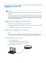
Page 18: ...gh the console port Prepare the following items before logging in through the console port An 8 core console cable with a crimped RJ 45 connector at one end and a DB 9 connector at the other end A con...

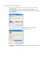
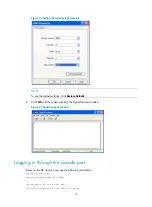
Page 19: ...nnection Description dialog box that appears type the name of the new connection in the Name text box and click OK Figure 22 Connection description 3 Select the serial port to be used from the Connect...

Page 20: ...Click OK and the system displays the HyperTerminal window Figure 25 HyperTerminal window Logging in through the console port Power on the AP and you can see the following information System is startin...

Page 21: ...following default login information Username admin Password h3capadmin IP address of VLAN interface 1 of the AP 192 168 0 50 with subnet mask 255 255 255 0 If the default IP address is changed perform...

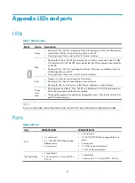
Page 22: ...curs during the AP initiation Flashing 1 Hz The AP cannot detect radio interfaces Flashing 8 Hz A fault occurs on the Ethernet interface or radio interface Green and blue Flashing green and blue 1 Hz...

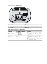
Page 23: ...rt description for the WA4620i ACN AP Port mark Standards and protocols Description ETH1 and ETH2 IEEE802 3 IEEE802 3u IEEE802 3af The Ethernet port can act as an uplink interface to access the Intern...

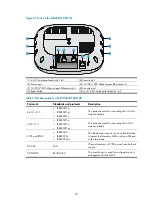
Page 24: ...1 2 3 IEEE802 1 1b IEEE802 1 1g IEEE802 1 1n The ports are used for connecting the 2 4 GHz antenna feeders 5G 1 2 3 IEEE802 1 1a IEEE802 1 1n IEEE802 1 1ac The ports are used for connecting the 5 GHz...

Page 25: ...e cable 17 local power supply 15 network 15 PoE power supply 14 power supply 14 console connecting cable 17 D data bits parameter 18 determining installation position 6 E electrical connecting console...

Page 26: ...upply 14 connecting power supply 14 installing antenna 6 installing AP 5 6 installing the AP on a ceiling 11 mounting the AP on a wall 7 verifying network connection for the fat AP 16 verifying networ...

Reviews: