background image


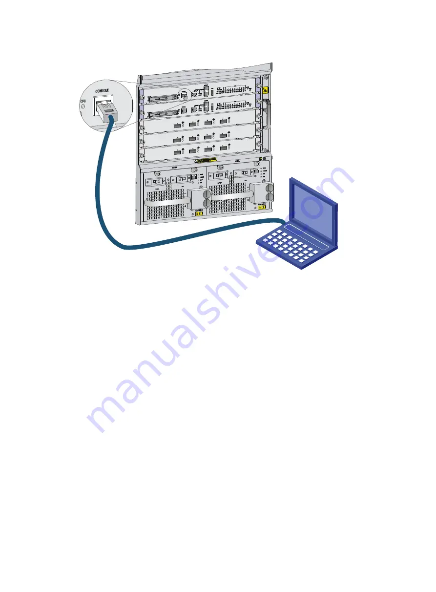
Figure 1 Connecting a console port to a terminal 


Setting terminal parameters 

To access the  device through the console port, you must run a terminal emulator program 
(TeraTermPro, PuTTY, or Tera Term) on the configuration terminal. For information about how to use 
a terminal emulator program, see the program's user guide. 

The following are the required terminal settings: 


Baud rate

—9600. 


Data bits

—8. 


Stop bits

—1. 


Parity

—none. 


Flow control

—none. 

Powering on the router 

Before powering on the router, verify the following items: 


The router has been steadily mounted.  


All the cards have been correctly installed.  


All the communication cables, fibers, power cords, and grounding cables have been correctly 
connected.  


The input power voltage meets the requirement of the router.  


The console cable has been correctly connected.  


The configuration terminal has been started, and the terminal parameters have been 
configured.  

Summary of Contents for SR8800-F

Page 1: ...H3C SR8800 F Router Series Installation Guide New H3C Technologies Co Ltd http www h3c com Document version 5W104 20221206 ...

Page 2: ...r respective owners Notice The information in this document is subject to change without notice All contents in this document including statements information and recommendations are believed to be accurate but they are presented without warranty of any kind express or implied H3C shall not be liable for technical or editorial errors or omissions contained herein Environmental protection This prod...

Page 3: ...guments that are optional x y Braces enclose a set of required syntax choices separated by vertical bars from which you select one x y Square brackets enclose a set of optional syntax choices separated by vertical bars from which you select one or none x y Asterisk marked braces enclose a set of required syntax choices separated by vertical bars from which you select a minimum of one x y Asterisk ...

Page 4: ...as a Layer 2 or Layer 3 switch or a router that supports Layer 2 forwarding and other Layer 2 features Represents an access controller a unified wired WLAN module or the access controller engine on a unified wired WLAN switch Represents an access point Represents a wireless terminator unit Represents a wireless terminator Represents a mesh access point Represents omnidirectional signals Represents...

Page 5: ...Documentation feedback You can e mail your comments about product documentation to info h3c com We appreciate your comments ...

Page 6: ...l safety recommendations 1 Electricity safety 1 Moving safety 1 ESD prevention 1 Laser safety 2 Examining the installation site 2 Weight support 2 Temperature 2 Humidity 2 Operating altitude 3 Cleanliness 3 EMI 3 Grounding 4 Power 4 Cooling 4 Space 5 Tools and equipment 6 ...

Page 7: ... safety grounds and wet floors Locate the emergency power off switch in the room before installation Shut the power off at once in case accident occurs Remove all external cables including power cords before moving the chassis Do not work alone when the router has power Always verify that the power has been disconnected Moving safety WARNING Hold the chassis handles firmly to move the router Do no...

Page 8: ... the total weight of the rack chassis cards and power supplies and all other components Additionally the floor loading plan must cover system expansion such as adding more cards Temperature CAUTION If condensation appears on the router when you move it to a high temperature environment dry the router before powering it on to avoid short circuits To ensure the correct operation of the router make s...

Page 9: ...ents Make sure the corrosive gases in the equipment room do not exceed the concentration limits as shown in Table 4 Table 4 Corrosive gas concentration limits in the equipment room Gas Average concentration mg m 3 Maximum concentration mg m 3 SO2 0 3 1 0 H2S 0 1 0 5 Cl2 0 1 0 3 HCI 0 1 0 5 HF 0 01 0 03 NH3 1 0 3 0 O3 0 05 0 1 NOX 0 5 1 0 EMI All electromagnetic interference EMI sources from outsid...

Page 10: ...mption varies by card type density and fan tray power consumption For more information about system power consumption calculation see Module power consumption and total power consumption 2 Select power supplies and determine the number of power supplies The total maximum output power of all power supplies must be higher than the system power consumption For more information about available power s...

Page 11: ... dimensions Table 5 Router dimensions and rack requirements Model Chassis dimensions Rack requirements SR8803 F Height 175 mm 6 89 in 4 RU Width 436 mm 17 17 in Depth 505 mm 19 89 in 420 mm 16 54 in for the chassis 61 mm 2 40 in for the cable management brackets at the chassis front 30 5 mm 1 20 in for the PoE terminal box A minimum of 0 8 m 2 62 ft in depth recommended A minimum of 61 mm 2 40 in ...

Page 12: ...of 0 8 m 2 62 ft in depth recommended A minimum of 100 mm 3 94 in between the front rack posts and the front door A minimum of 420 mm 16 54 in between the front rack posts and the rear door NOTE The signal cables and power cords are routed through the front of the chassis If you use power cords that has a conductor cross section area of a minimum of 16 sq mm 0 02 sq in leave more space between the...

Page 13: ...iliary tools ESD wrist strap Hair brush Paper knife Hand bellows Electric iron Solder wire Ladder Cable stripper Vacuum cleaner Crowbar Rubber hammer Tools for fiber optic cleaning Lint free paper Optical fiber microscope Equipment Multimeter 500 V Megohmmeter for measuring the insulation resistance Error detector Optical power meter Earth resistance tester ...

Page 14: ...ng cable management bracket and mounting brackets 4 Installing the cable management bracket 4 Installing mounting brackets 4 Optional Installing an air filter 5 Mounting the router in the rack 6 Grounding the router 7 Connecting the grounding cable to a grounding strip 7 Grounding the router through the PE wire of an AC power supply 8 Grounding the router through the RTN wire of a DC power supply ...

Page 15: ...irements A 19 inch rack is ready for use For information about installing a rack see the rack installation guide The rack is sturdy and reliably grounded No debris or obstacles exist inside or around the rack Make sure the rack has enough space to accommodate the router As a best practice to maintain the rack stability install the router at the rack bottom To mount multiple devices in a rack insta...

Page 16: ...he slide rails see the installation guide shipped with the slide rails Table 1 Slide rails available for the router Router model Chassis weight with full configuration Available slide rails Slide rail model Max load bearing capacity Adjustment range Occupied space SR8803 F 29 kg 63 93 lb LSXM1BSR 450 kg 992 06 lb 630 to 900 mm 24 80 to 35 43 in 1 RU LSTM1KSGD0 280 kg 617 28 lb 300 to 500 mm 11 81 ...

Page 17: ...alling cage nuts Before mounting the chassis in the rack attach cage nuts to the front rack posts 1 As shown in Figure 2 determine the positions of the cage nuts according to the holes on the mounting brackets and the positions of the slide rails 2 Install cage nuts into the marked square holes on the front rack posts Figure 2 Determining the cage nut installation positions SR8805 F 1 Cage nut ins...

Page 18: ... with two mounting brackets and the one with the cable management bracket screw holes is the left mounting bracket Figure 3 Attaching the cable management bracket to the left mounting bracket SR8805 F 1 Left mounting bracket 2 Cable management bracket 3 Screw hole for installing the cable management bracket 4 Screw for fixing the cable management bracket to the left mounting bracket Installing mou...

Page 19: ...g the router in the rack To install the air filter 1 Unpack the air filter and the metal rails 2 Attach the metal rails to the left of the router Align the mounting holes on the metal rails with the mounting holes above and below the inlet air vent as shown by callout 1 in Figure 5 3 Fasten the mounting screws to fix the metal rails 4 Insert the air filter along the metal rails to the end as shown...

Page 20: ...ight tip the router damaging the router or even causing bodily injury To mount the router in the rack 1 Move the chassis to face the rear of the chassis toward the front of the rack 2 To lift the router use a minimum of two persons or use a mechanical lift if necessary Lift the router until the bottom of the router is a little higher than the slide rails on the rack 3 Gently place the router on th...

Page 21: ...ect the grounding cable to the grounding system in the equipment room Do not connect it to a fire main or lightning rod If a grounding strip is available at the installation site connect the grounding cable through the grounding strip To connect the grounding cable 1 Unpack the grounding cable The grounding cable provided with the router is compliant with the NEBS standards 2 Remove the grounding ...

Page 22: ...e of the AC power supply is correctly grounded at the power distribution room or AC power supply transformer side Make sure the PE connector on the router is correctly connected to the PE wire of the AC power supply You can ground the router through the PE wire of the AC power supply as shown in Figure 8 if the following conditions exist The router is AC powered No grounding strip is available at ...

Page 23: ...e DC egress of the DC power cabinet You can ground the router through the return RTN wire of the DC power supply as shown in Figure 9 if the following conditions exist The router is powered by a 48 VDC power supply No grounding strip is available at the installation site Figure 9 Grounding the router through the RTN wire of the DC power supply PGND busbar RTN busbar 48V busbar DC power box Ground ...

Page 24: ...r supply system 4 Installing a power supply adapter 4 Installing a power supply in the chassis 5 Connecting the power cord 6 Optional Installing a CF card for an MPU 15 Optional Installing a transceiver module 16 Installing an XFP QSFP SFP SFP QSFP28 transceiver module 17 Installing a CFP transceiver module 17 Connecting an E1 cable 18 ...

Page 25: ...r how to ground your router see Grounding the router 2 Wear the wrist strap 3 Tighten the wrist strap to keep good skin contact Make sure the resistance reading between your body and the ground is between 1 and 10 megohms 4 As shown in Figure 1 attach the ESD wrist strap to the chassis by either of the following methods Insert the ESD wrist strap into the ESD socket on the chassis Attach the ESD w...

Page 26: ...e card 4 As shown by callout 1 in Figure 2 hold the card by the front panel with one hand and support the card bottom with the other Slide the card steadily into the slot along the guide rails 5 As shown by callout 2 in Figure 2 when most part of the card is inserted in the slot press the ejector levers on the card outward 6 Push the card until the positioning pin on card touches the hole on the c...

Page 27: ... in the router 3 Unpack the subcard 4 Install the subcard in the base card a Remove the filler panel if any from the target slot on the base card as shown by callout 1 in Figure 3 Keep the removed filler panel secure for future use b Open the ejector levers on the subcard as shown by callout 2 in Figure 3 c Gently push the subcard with bottom up into the slot along the guide rails until the ejecto...

Page 28: ...nputs You can supply either AC or DC power for the switch For information about the power supplies available for the switch see Power supplies To use a power adapter first install it in the chassis and then install power supplies in the power adapter For how to install a power supply in a power adapter see Installing a power supply in the chassis Installing a power supply adapter CAUTION Do not in...

Page 29: ...e chassis and insert it again in case of misalignment 4 Use a Phillips screwdriver to fasten the captive screws on the adapter to secure the adapter in the chassis If you cannot fasten the captive screws tightly check the adapter installation Figure 4 Installing a power supply adapter LSQM1PWRSPB Installing a power supply in the chassis CAUTION Before installing a power supply make sure the switch...

Page 30: ...ng the guide rails into the slot to firmly seat it into the backplane as shown by callout 1 in Figure 5 When a misalignment occurs pull out the power supply first and push it in again to avoid damage to the power supply and the connection terminals on the backplane 5 Fasten the captive screws on the power supply to secure the power supply into the chassis as shown by callout 2 in Figure 5 If the c...

Page 31: ...wer supplies prepare a 16A power strip and make sure the AC power supply system can provide enough power For information about power cord plugs and connectors used in different countries or regions see AC power cords Connecting the power cord for a PSR320 A PSR650 A power supply 1 Insert the two ends of the bail latch to the holders on the left of the power socket Then pull the bail latch to the l...

Page 32: ...ck the power cord and verify the power cord model is correct The PSR1200 A power supply uses a 16A AC power cord 2 Connect the power cord to the power socket and ensure a good contact 3 Use a releasable cable tie to secure the power cord to the handle of the power supply 4 Connect the other end of the power cord to the AC power source ...

Page 33: ...e model is correct The PSR1400 A uses a 16A AC power cord 2 Connect the female connector of the power cord to the power receptacle on the power supply and ensure good contact 3 Use a releasable cable tie to secure the power cord to the handle of the power supply 4 Connect the other end of the power cord to an AC power source 5 Switch on the power supply 6 Verify the power supply input status LED I...

Page 34: ...0 A uses a 16A AC power cord 2 Use a Phillips screwdriver to remove the screws from the power cord retainer suite and remove the right part of the retainer suite 3 Connect the female connector of the power cord to the power receptacle on the power supply and ensure good contact 4 Secure the right part of the power cord retainer suite to retain the power cord 5 Connect the other end of the power co...

Page 35: ...pply 1 Unpack the power cord and make sure the power cord model is correct The PSR2500 12AHD power supply uses a 16A AC power cord or a high voltage DC power cord 2 Connect the female connector of the power cord to the power receptacle on the power supply Push the tab on the connector to secure the connector in position 3 Connect the other end of the power cord to a power source ...

Page 36: ...D power supply 1 Remove the protection cover from the power supply 2 Loosen the screws on the wiring terminals with a Phillips screwdriver 3 Connect the end of the blue DC power cord marked with to the negative terminal on the power supply and fasten the screw 4 Connect the end of the black DC power cord marked with to the positive terminal on the power supply and fasten the screw 5 Put the protec...

Page 37: ...t secures the terminal block plug to the chassis and remove the terminal block plug Figure 12 Removing the terminal block plug 2 Unpack the DC power cord provided with the power supply Insert the wire marked with to the negative terminal on the terminal block and fasten the screw Insert the wire marked with to the positive terminal and fasten the screw ...

Page 38: ...R1400 D PSR2500 12D power supply WARNING Before connecting the power cord for a PSR1400 D PSR2500 12D power supply make sure the DC power source circuit breakers are turned off The power cord connection procedure is similar for the PSR1400 D and PSR2500 12D power supplies The following procedure uses the PSR1400 D power supply as an example To connect the power cords for the PSR1400 D 1 Loosen the...

Page 39: ...n turn and screw up the M6 nut with the M6 socket wrench Repeat this step for the other three terminals 6 Put the protection cover on the wiring terminals and faster the screws 7 Connect the other ends of the DC power cords to a DC power source Figure 15 Connecting the power cord for a PSR1400 D power supply Optional Installing a CF card for an MPU An MPU with a CF card protection cover is shipped...

Page 40: ... 3 After the router is powered on you can verify the running status of the CF card by using either of the following methods Verify the status of the CFS LED on the MPU If the LED is steady on the CF card is installed correctly For more information about the CFS LED see CF card status LED Verify the CF card running status at the CLI For more information see Hardware management and maintenance Figur...

Page 41: ...e transceiver module Then correctly orient the transceiver module and align it with the fiber port and push it gently into the port until you feel it snap into place Transceiver modules and fiber ports have disorientation rejection designs If you cannot insert a transceiver module easily into a port the orientation might be wrong Remove and reorient the transceiver module In case of limited space ...

Page 42: ...aptive screws on the transceiver module to secure it in place If a screw cannot be fastened adjust the CFP module and the screw and re fasten the screw or remove the CFP module and then reinstall it 5 Connect a fiber to the module For the installation procedure see Connecting the router to the network Figure 19 Installing a CFP transceiver module Connecting an E1 cable 1 Wear an ESD wrist strap an...

Page 43: ...minal parameters 2 Powering on the router 2 Configuring the router 3 Configuring authentication on a user interface 4 Verifying the network configuration 4 Connecting the router to the network 4 Connecting your router to the network through twisted pair cables 4 Connecting your router to the network through optical fibers 5 Testing connectivity 5 ...

Page 44: ...SR8800 F Routers Fundamentals Configuration Guide Accessing the router for the first time The first time you access the router you must use a console cable to connect the console port on the router to a configuration terminal a PC for example If two MPUs are installed in the router you can connect the console terminal to the console port on either of the MPUs Setting up the configuration environme...

Page 45: ...d terminal settings Baud rate 9600 Data bits 8 Stop bits 1 Parity none Flow control none Powering on the router Before powering on the router verify the following items The router has been steadily mounted All the cards have been correctly installed All the communication cables fibers power cords and grounding cables have been correctly connected The input power voltage meets the requirement of th...

Page 46: ...ile flash temp system bin is self decompressing Done System image is starting Finished running batch file Line con0 is available Press ENTER to get started 3 Press Enter When the prompt Sysname appears you can configure the router After powering on the router verify the following items The cooling system is operating You can hear fan rotating noise and feel air being blown out All the system statu...

Page 47: ... any view Task Command Display the name model and running operating system version of the router display version Display the current configuration of the router display current configuration Display the interface status and configuration display interface brief Display the IP configuration information of the specified or all Layer 3 interfaces display ip interface brief Display information about a...

Page 48: ...tical fiber To connect your router to the network through an optical fiber 1 Install the transceiver modules into the fiber ports of the router and the peer device 2 Remove the dust covers of the optical fiber connectors and clean both ends of the optical fiber 3 Connect the optical fiber to the transceiver modules a Remove the dust plugs of the transceiver modules b Connect one end of the optical...

Page 49: ...6 debugging commands in H3C SR8800 F Routers Network Management and Monitoring Command Reference ...

Page 50: ...roubleshooting on startup 1 Troubleshooting the router during the operation 2 Troubleshooting the power supply system 2 Troubleshooting the fans 3 Troubleshooting the MPUs 3 Troubleshooting the service modules 3 Troubleshooting interfaces 4 Troubleshooting CF cards 4 Technical support 5 ...

Page 51: ...LED status on the service modules see Service module LEDs If you cannot locate failures by using the methods in this chapter contact the local agents or H3C Support For more information see Technical support Troubleshooting the system Troubleshooting on startup After you power on the router if the router operates correctly the startup information appears on the console terminal If the console term...

Page 52: ...endix C LEDs NOTE After the power source is disconnected from the power supply it is correct that the LEDs stay on for a period of time If the LEDs do not conform to the status mentioned above the power supply is operating incorrectly To troubleshoot the power supply system 1 Verify that the power supply is switched on 2 Examine whether the power supply is over temperature When a power supply is o...

Page 53: ...ated slot According to the slot number of an MPU you can identify the associated LEDs for the MPU For more information see MPU LEDs To troubleshoot the MPU 1 Verify that the power supply is operating correctly For more information see Troubleshooting the power supply system 2 Verify that the MPU model is compatible with the chassis For more information see MPUs 3 Press the RESET button on the MPU ...

Page 54: ...on of the interface For how to correctly connect the cable to a copper port with an RJ 45 connector or to a fiber port see Connecting your router to the network through twisted pair cables 3 Verify that the cable is not broken Use the cable to connect two interfaces of the same type that are operating correctly If the LEDs of the two interfaces are on the cable is normal Otherwise the cable is bro...

Page 55: ...pport Technical support If the failures still exist contact the agents or H3C Support To report the failures prepare the following information Arrival time of the router Serial number of the chassis located on a label on the right of the rear panel Software version Maintenance agreement or warranty card Brief problem description Brief explanation of the troubleshooting measures that have been take...

Page 56: ...er supply 2 Replacing a card 4 Replacing a subcard 5 Replacing a fan tray 6 Removing a fan tray 6 Installing a fan tray 7 Replacing an air filter 7 Replacing a CF card 8 Replacing a transceiver module 9 Replacing an XFP QSFP SFP SFP QSFP28 transceiver module 10 Replacing a CFP transceiver module 10 Replacing an E1 cable 11 ...

Page 57: ...ace FRUs when the router is operating Replacing the power supply system Replacing a power supply adapter 1 Prepare an antistatic mat to place the removed power supply adapter 2 Wear an ESD wrist strap and make sure it makes good skin contact and is reliably grounded For more information see Attaching an ESD wrist strap 3 Use a Phillips screwdriver to loosen the captive screws on the power supply a...

Page 58: ...allation flow Do not install AC and DC power supplies on the same router The power supplies on a router must be the same model To avoid device damage power off the router before replacing two power supplies on the router with a different model For a router using two power supplies make sure each power supply has a separate circuit breaker Before replacing a power supply turn off the circuit breake...

Page 59: ...ower cord from the power supply 5 Use a Phillips screwdriver to loosen the captive screws on the power supply as shown by callout 1 in Figure 4 6 Remove the power supply as shown by callout 2 in Figure 4 a Hold the power supply handle with one hand and support the bottom of the power supply with the other b Gently pull the power supply out 7 Remove the power adapter The procedures for removing a p...

Page 60: ...out the reboot and display device commands see device management commands in H3C SR8800 F Routers Fundamentals Command Reference CAUTION To replace an MPU or service module first remove all its cables The replacement procedure is the same for the cards To replace a card 1 Prepare an antistatic mat to place the removed card 2 Wear an ESD wrist strap and make sure it has a good skin contact and is c...

Page 61: ...rd This section describes the procedure for replacing a subcard on a base card The subcards are hot swappable To replace a subcard 1 Put on an ESD wrist strap and make sure the wrist strap makes good skin contact and is correctly grounded For more information see Attaching an ESD wrist strap 2 Use a Phillips screwdriver to loosen the mounting screws on the subcard as shown by callout 1 in Figure 6...

Page 62: ...static mat or the original package to place the removed fan tray 2 Wear an ESD wrist strap and make sure it has a good skin contact and is correctly grounded For more information see Attaching an ESD wrist strap 3 Use a screwdriver to remove the captive screws on the fan tray as shown by callout 1 in Figure 7 4 Supporting the fan tray by its bottom with one hand hold the fan tray handle with the o...

Page 63: ...s a close contact with the backplane 4 Use a screwdriver to fasten the captive screws on the fan tray 5 Verify that the fan tray is installed correctly by using either of the following methods Verify the status of the FAN LEDs on the MPU If the OK LED is on the fan tray is installed successfully For more information about the FAN LEDs see Fan tray status LEDs Verify the fan status by using the dis...

Page 64: ... card might be damaged The CF card is installed on the MPU of the router To replace a CF card 1 Verify the CF card LED status If the LED is on you cannot remove the CF card You must use the umount cfa0 command at the CLI to unmount the CF card and wait until the CF card LED is off After you execute the umount cf command if you want to continue to use the CF card execute the mount cf command in use...

Page 65: ...e new CF card all the way into the CF card slot until the eject button resets 5 Push the CF card cover inward and use a Phillips screwdriver to fasten the screw on the CF card protection cover Skip this step if the MPU does not have a CF card protection cover Figure 9 Replacing a CF card Replacing a transceiver module WARNING Do not stare into any open apertures of operating transceiver modules or...

Page 66: ...he horizontal position 4 Grasp the clasp on the module and carefully pull the module out of the slot If you use force at an angle you can hardly pull the transceiver module out and the transceiver module or fiber port might be damaged If you forcibly pull out of the transceiver module without pivoting the bail latch down the triangular pin of the transceiver module and the fiber port might be dama...

Page 67: ...ged Figure 11 Removing the CFP transceiver module 5 Put the dust plug on the removed module and put the removed module into its original shipping materials 6 Install a new module For the installation procedures see Installing a CFP transceiver module Replacing an E1 cable 1 Wear an ESD wrist strap and make sure it makes good skin contact and is reliably grounded For more information see Attaching ...

Page 68: ...cal specifications 1 Chassis views 1 SR8803 F 1 SR8805 F 2 SR8808 F 3 SR8812 F 4 Technical specifications 4 Weights and dimensions 4 Module power consumption and total power consumption 7 Heat dissipation 10 Environmental specifications 10 Noise 11 ...

Page 69: ...available chassis models and accessories vary by country and region This document describes only the preceding models For the chassis models and accessories available in your country or region contact the local H3C marketing personnel SR8803 F Figure 1 SR8803 F front and rear views 1 Power supply section 2 MPU section 3 Service module section 4 Fan tray section 5 PoE PEM reserved 1 2 3 4 5 ...

Page 70: ...2 SR8805 F Figure 2 SR8805 F front view 1 MPU section 2 Service module section 3 Power supply section 4 Fan tray section 3 1 2 3 4 ...

Page 71: ...3 SR8808 F Figure 3 SR8808 F front view 1 MPU section 2 Service module section 3 Power supply section 4 Fan tray section 3 1 2 3 4 ...

Page 72: ...hts and dimensions Model Weight full configuration Height Width Depth SR8803 F 29 kg 63 93 lb 175 mm 6 89 in 4 RU 436 mm 17 17 in 420 mm 16 54 in SR8805 F 56 kg 123 46 lb 441 mm 17 36 in 10 RU 436 mm 17 17 in 420 mm 16 54 in SR8808 F 74 kg 163 14 lb 575 mm 22 64 in 13 RU 436 mm 17 17 in 420 mm 16 54 in SR8812 F 95 kg 209 44 lb 708 mm 27 87 in 16 436 mm 17 17 in 420 mm 16 54 in 1 1 2 3 4 3 ...

Page 73: ...5 71 in 352 mm 13 86 in SPC GP44XP4LA 3 55 kg 7 83 lb 40 mm 1 57 in 399 mm 15 71 in 352 mm 13 86 in SPC GP44XP4LC 3 6 kg 7 94 lb 40 mm 1 57 in 399 mm 15 71 in 352 mm 13 86 in CSPC XP2LA1 2 93 kg 6 46 lb 40 mm 1 57 in 399 mm 15 71 in 352 mm 13 86 in CSPC XP4LB 2 93 kg 6 46 lb 40 mm 1 57 in 399 mm 15 71 in 352 mm 13 86 in CSPC XP8LB 3 44 kg 7 58 lb 40 mm 1 57 in 399 mm 15 71 in 352 mm 13 86 in CSPC ...

Page 74: ...6 18 in MIC GP20L 0 50 kg 1 10 lb 37 mm 1 46 in 171 mm 6 73 in 157 mm 6 18 in MIC XP2L 0 29 kg 0 64 lb 18 mm 0 71 in 171 mm 6 73 in 157 mm 6 18 in MIC XP2L LAN 0 28 kg 0 62 lb 18 mm 0 71 in 171 mm 6 73 in 157 mm 6 18 in MIC XP4L1 0 30 kg 0 66 lb 18 mm 0 71 in 171 mm 6 73 in 157 mm 6 18 in MIC CP1L 0 55 kg 1 21 lb 37 mm 1 46 in 171 mm 6 73 in 157 mm 6 18 in MIC CQ1L1 0 50 kg 1 10 lb 37 mm 1 46 in 1...

Page 75: ...5 7 kg 12 57 lb 128 mm 5 04 in 196 mm 7 72 in 382 mm 15 04 in Table 5 Fan tray weights and dimensions lying flat on a workbench Model Net weight Height Width Depth SR8803 F fan tray 0 9 kg 1 98 lb 27 mm 1 06 in 115 mm 4 53 in 338 mm 13 31 in SR8805 F fan tray 1 6 kg 3 53 lb 27 mm 1 06 in 203 mm 7 99 in 365 mm 14 37 in SR8808 F fan tray 2 2 kg 4 85 lb 28 mm 1 10 in 331 mm 13 03 in 365 mm 14 37 in S...

Page 76: ...y card model and state Table 6 shows the power consumption for different card models The static power consumption of a card refers to the power consumed by the card under the following conditions The card is running All ports on the card are down No transceiver module is available on the optical interface of the card The dynamic power consumption of a card refers to the power consumed by the card ...

Page 77: ...P8L 9 70 W 17 W PIC PSP4L 9 70 W 18 W PIC PS2G4L 9 3 W 16 W PIC PUP1L 14 3 W 19 W PIC XP1L 12 5 W 23 7 W MIC GT20L 9 2 W 11 9 W MIC ET16L 8 6 W 8 7 W MIC CLP2L 9 8 W 10 9 W MIC CLP4L 9 8 W 12 9 W MIC GP4L 0 8 W 5 5 W MIC GP8L 0 6 W 4 7 W MIC GP10L1 2 1 W 7 9 W MIC GP10L V2 9 3 W 9 4 W MIC SP4L 9 6 W 13 5 W MIC SP8L 14 W 16 3 W MIC GP20L 7 6 W 23 W MIC XP2L 10 W 13 W MIC XP2L LAN 6 W 9 W MIC XP4L1 ...

Page 78: ... 28 W 50 W Heat dissipation Heat dissipation is measured in BTU h and 1 W equals 3 4121BTU h The heat dissipation of a router depends on its power consumption To calculate heat dissipation of the router assume 90 power consumption is converted to heat and the efficiency of the power supply is 80 Heat dissipation hour of the router is 0 9 total power consumption of the cards plus power consumption ...

Page 79: ...The sound pressure level of the router varies by fan speed Table 9 Sound pressure levels Model Sound pressure level At low fan speed At middle fan speed At full fan speed SR8803 F 49 8 dBA 51 6 dBA 56 7 dBA SR8805 F 51 6 dBA 54 6 dBA 56 1 dBA SR8808 F 53 6 dBA 56 2 dBA 57 7 dBA SR8812 F 53 5 dBA 55 8 dBA 56 7 dBA ...

Page 80: ...4 CMPE cards 6 Subcards 7 OAA modules 10 Service module ordering guide 10 Power supplies 10 Overview 10 Ordering guide 11 Fan trays 12 Fan tray overview 12 Fan tray ordering guide 12 Air filters 13 Air filter overview 13 Air filter ordering guide 13 CF cards 13 CF card overview 13 CF card ordering guide 13 DC power cords 13 AC power cords 14 ...

Page 81: ...C ports for IRF connections only using SFP transceiver modules SR8805 F SR8808 F SR8812 F CSR07SRPUB1 4 GB 1 console port 1 network management port 1 USB port 2 10 GE MCC ports for IRF connections only using SFP transceiver modules 1 CF card slot SR8805 F SR8808 F SR8812 F CSR07SRPUC1 4 GB 1 console port 1 network management port 1 USB port 1 CF card slot SR8805 F CSR07SRPUD3 8 GB or 16 GB 1 conso...

Page 82: ...the chassis indicates that the MPU is not compatible with the chassis Service modules CSPC and SPC cards Table 3 CSPC and SPC card specifications Model Description Connector Number of ports Port speed CSPC GT48LA1 48 port 10 100 1000BASE T Ethernet interface module RJ 45 48 10 100 1000 Mbps CSPC GE24L E 24 port 1000BASE X Ethernet combo interface line processing unit RJ 45 24 10 100 1000 Mbps LC 2...

Page 83: ...P4L A 44 port 1000BASE X Ethernet optical interface module 4 port 10GBASE Ethernet optical interface module LC 44 100 Mbps 1000 Mbps 10 100 1000 Mbps 4 10 Gbps SPC GP44XP4L C 44 port 1000BASE X Ethernet optical interface module 4 port 10GBASE Ethernet optical interface module LC 44 100 Mbps 1000 Mbps 10 100 1000 Mbps 4 10 Gbps CSPC XP2LA1 2 port 10GBASE Ethernet optical interface module LC 2 10 Gb...

Page 84: ...S 4 CSPEX 1404S 4 CSPEX 1504S 4 Table 5 Compatibility matrixes between CSPEX cards and subcards Subcard model CSPEX 1504S C SPEX 1404S CSPEX 1304S CSPEX 1204 CSPEX 1104 E PIC GP10L Not supported Not supported Supported in subslots 1 and 2 Not supported in subslot 3 or 4 Not supported PIC TCP8L Supported in subslots 1 and 2 Not supported in subslot 3 or 4 Not supported Supported in subslots 1 and 2...

Page 85: ...d in subslots 3 and 4 Supported a maximum of 3 MIC GP8L Not supported Not supported Not supported in subslot 1 or 2 Supported in subslots 3 and 4 Not supported MIC GP10L1 Not supported Not supported Not supported in subslot 1 or 2 Supported in subslots 3 and 4 Not supported MIC GP10L V 2 Supported Supported in subslots 1 2 and 3 Not supported in subslot 4 Not supported Supported MIC GP20L Supporte...

Page 86: ... Do not mix CSPEX 1304S CSPEX 1404S or CSPEX 1504S card with other CSPEX cards than these three on an SR8803 F router A CSPEX 1104 E base card supports a maximum of three MIC XP4L1 or MIC GP4L subcards or a maximum of three of them in combinations CMPE cards Table 6 CMPE card specifications Model Subslot quantity CMPE 1104 4 Table 7 Compatibility matrixes between CMPE cards and subcards Subcard mo...

Page 87: ...bslot restrictions on a CMPE base card depend on the subcard mode For more information about the subcard mode see device management in H3C SR8800 F Routers Fundamentals Configuration Guide Subcards PIC subcards Table 8 PIC subcard specifications Model Description Connector Number of ports Port speed PIC GP10L 10 port 1000BASE X optical interface card SFP LC LC 10 100 Mbps 1000 Mbps 10 100 1000 Mbp...

Page 88: ...6 male connector HM96 male 16 E1 MIC CLP2L 2 port OC 3 STM 1 channelized POS optical interface card SFP LC LC 2 155 Mbps OC 3 STM 1 MIC CLP4L 4 port OC 3 STM 1 channelized POS optical interface card SFP LC LC 4 155 Mbps OC 3 STM 1 MIC SP4L 4 port OC 3c STM 1c POS ATM or 1 port OC 12c STM 4c POS ATM optical interface card SFP LC LC 4 155 Mbps OC 3 STM 1 1 622 Mbps OC 12 STM 4 MIC SP8L 8 port OC 3c ...

Page 89: ...00 Mbps 10 100 1000 Mpbs 1000 Mbps 10 Gbps MIC XP5L 5 port 10GBASE R W Ethernet optical interface card SFP LC LC 5 100 Mbps 10 100 1000 Mpbs 1000 Mbps 10 Gbps MIC XP5L1 5 port 10GBASE R W Ethernet optical interface card SFP LC LC 5 100 Mbps 10 100 1000 Mbps 1000 Mbps 10 Gbps MIC QP1L 1 port 40G Ethernet optical interface card QSFP LC LC 1 40 Gbps 4 10 Gbps MIC CP1L 1 port 100G optical interface ca...

Page 90: ...r requirements for interface types and interface quantity in the network For more information about the service modules see Table 3 Support for some software features depends on the service module model For more information contact H3C Support Power supplies Overview CAUTION As a best practice use an air switch that has a rated current not less than 1 2 times the maximum input current of the power...

Page 91: ...ed on an SR8800 F router must be the same type AC or DC and model Support for power supply models depends on the SR8800 F chassis model You can order power supplies according to the power supply conditions at the installation site and power consumption requirements as shown in Table 11 and Table 12 Make sure the total maximum output power of the ordered power supplies is greater than the overall p...

Page 92: ...not be installed into the chassis Fan trays Fan tray overview The router uses fan trays that can automatically adjust the fan speed to meet the cooling requirements Table 13 Fan tray specifications Fan tray Number of fans Fan diameter Maximum rotating speed Maximum air flow rate SR8803 F fan tray 3 92 mm 3 62 in 3800 RPM 165 CFM SR8805 F fan tray 6 92 mm 3 62 in 3800 RPM 330 CFM SR8808 F fan tray ...

Page 93: ...r the device A CF card can store startup files configuration files and logs CF card ordering guide For information about the MPUs with a CF card slot see Table 1 Table 14 lists the CF card specifications Table 14 CF card specifications CF card model Description Storage capacity CF 4G Storage medium Compact Flash card 4G 4 GB DC power cords A DC power cord is used to connect a DC power supply of a ...

Page 94: ...pes for 16A AC power cords The 0404A0RP and 0404A0RQ AC power cords are available for the PSR2500 12AHD power supply Table 16 10A AC power cords used in different countries or regions 1 Plug type Code Length Countries or regions where the type of power cords conforms to local safety regulations and can be used legally Other countries or regions using this type of power cords Countries or regions s...

Page 95: ...ng this type of power cords Countries or regions seldom using this type of power cords F type 04041056 3 m 9 8 ft Holland Denmark Sweden Finland Norway Germany France Austria Belgium and Italy Indonesia Türkiye Russia and CIS N A Plug outline Power cord outline Connector outline 4 Plug type Code Length Countries or regions where the type of power cords conforms to local safety regulations and can ...

Page 96: ...Japan N A N A Plug outline Power cord outline Connector outline 6 Plug type Code Length Countries or regions where the type of power cords conforms to local safety regulations and can be used legally Other countries or regions using this type of power cords Countries or regions seldom using this type of power cords I type 04040888 3 m 9 8 ft Australia N A N A Plug outline Power cord outline Connec...

Page 97: ...wer cords conforms to local safety regulations and can be used legally Other countries or regions using this type of power cords Countries or regions seldom using this type of power cords L type 04041120 3 m 9 8 ft Italy N A N A Plug outline Power cord outline Connector outline 9 Plug type Code Length Countries or regions where the type of power cords conforms to local safety regulations and can b...

Page 98: ...regions using this type of power cords Countries or regions seldom using this type of power cords B type 0404A063 3 m 9 8 ft Canada and U S A Mexico Argentina Brazil Columbia Venezuela Thailand Peru Philippine and A6 countries or regions N A Plug outline Power cord outline Connector outline 3 Plug type Code Length Countries or regions where the type of power cords conforms to local safety regulati...

Page 99: ...d Norway Germany France Austria Belgium and Italy Indonesia Türkiye Russia and CIS N A Plug outline Power cord outline Connector outline 5 Plug type Code Length Countries or regions where the type of power cords conforms to local safety regulations and can be used legally Other countries or regions using this type of power cords Countries or regions seldom using this type of power cords B type 040...

Page 100: ...utline Connector outline 7 Plug type Code Length Countries or regions where the type of power cords conforms to local safety regulations and can be used legally Other countries or regions using this type of power cords Countries or regions seldom using this type of power cords N A 0404A0RP 3 m 9 8 ft China mainland N A N A Plug outline Power cord outline Connector outline 8 Plug type Code Length C...

Page 101: ...sed legally Other countries or regions using this type of power cords Countries or regions seldom using this type of power cords I type 04043396 3 m 9 8 ft Mainland China N A N A Plug outline Power cord outline Connector outline L type 0404A0RQ 3 m 9 8 ft Mainland China N A N A Plug outline Power cord outline Connector outline ...

Page 102: ... tray status LEDs 4 Card status LEDs 4 MPU active standby status LED 5 Service module LEDs 6 CSPC SPC LEDs 6 CSPEX CMPE card LED 7 Subcard LEDs 7 OAA module LEDs 10 Power supply LEDs 10 PSR320 A PSR650 A PSR650 D PSR1200 A PSR1200 D power supply LED 10 PSR1400 A PSR2500 12AHD PSR2500 12D power supply LEDs 11 PSR1400 D power supply LEDs 12 ...

Page 103: ...ndby status LED Service module LEDs CSPC SPC LEDs Subcard LEDs OAA module LEDs Power supply LEDs PSR320 A PSR650 A PSR650 D PSR1200 A PSR1200 D power supply LED PSR1400 A PSR2500 12AHD PSR2500 12D power supply LEDs PSR1400 D power supply LEDs MPU LEDs Unless otherwise stated the flashing frequency of the LEDs in this section is 0 5 Hz Figure 1 LEDs on the CSR07SRPUB1 1 CF card status LED CFS 2 Man...

Page 104: ...LED See Table 5 Power status LED For CSR07MPUA1 CSR07SRPUB1 CSR07SRPUC1 and CSR07SRPUD3 see Table 6 For CSR07SRPUA1 see Table 7 Fan tray status LED For CSR07MPUA1 CSR07SRPUB1 CSR07SRPUC1 and CSR07SRPUD3 see Table 8 For CSR07SRPUA1 see Table 9 Card status LED For CSR07SRPUA1 see Table 10 For CSR07SRPUB1 CSR07SRPUC1 and CSR07SRPUD3 see Table 11 For CSR07MPUA1 see Table 12 for the MPU status LED and ...

Page 105: ...on Status Description Flashing The port is sending or receiving data Steady on A link is present Off No link is present Power status LEDs Table 6 Power status LED description OK and FAIL OK LED status FAIL LED status Description Steady on Off All power supplies are operating correctly Off Steady on A power supply is not outputting power because one of the following condition exists The module is f...

Page 106: ...y Off Steady red A fan problem is present or the fan tray is not present Off Off The router is not powered on Table 9 Fan tray status LED description 2 Status Description Steady green The fan tray is operating correctly Steady red A fan problem has occurred or the fan tray is not present Off The router is not powered on Card status LEDs Before the active MPU starts up all card status LEDs are off ...

Page 107: ...ng up or faulty Off Off No card is present Table 12 MPU status LED description CSR07MPUA1 Status Description Flashing The card is operating correctly Off The card is starting up or faulty Table 13 Service module status LED description CSR07MPUA1 RUN LED status ALM LED status Description Flashing Off At least one card is operating correctly Fast flashing Steady on At least one card is loading softw...

Page 108: ...nk is present Off No link is present SFP port LEDs Table 17 SFP port LED description Status Description Flashing The port is receiving or sending data Steady on A link is present Off No link is present XFP port LEDs Table 18 XFP port LED description LINK LED status ACT LED status Description Steady on Flashing The port is receiving or sending data Steady on Off A link is present Off Off No link is...

Page 109: ...r second The card is operating correctly Fast flashing green about eight times per second The card is starting up If the LED keeps fast flashing the card has failed registration Subcard LEDs PIC subcard LEDs Table 22 PIC subcard LEDs LEDs PIC subcard Description GE SFP port LED PIC GP10L PIC PS2G4L See Table 23 10 GE XFP port LED PIC XP1L See Table 24 WAN port LED PIC TCP8L PIC PSP4L PIC PUP1L PIC...

Page 110: ... Table 26 MIC subcard LEDs LEDs PIC subcard Description RJ 45 port status LED MIC GT20L See Table 15 SFP port status LED MIC XP5L MIC XP2L MIC XP2L LAN MIC XP4L1 MIC XP5L1 MIC XP8L See Table 17 CFP port status LED MIC CP1L See Table 20 Combo interface status LED MIC GP4L See Table 27 GE SFP port status LED MIC GP8L MIC GP10L1 MIC GP10L V2 MIC GP20L MIC GP20L1 See Table 28 QSFP port LED MIC QP1L Se...

Page 111: ...iption LINK ACT Flashing green The port is sending or receiving data Steady green A link is present Off No link is present Table 29 QSFP port LED description Status Description Flashing The port is receiving or sending data Steady on A link is present Off No link is present Table 30 QSFP28 port LED description Status Description Flashing The port is receiving or sending data Steady on A link is pr...

Page 112: ...on the port Steady green A link is present on the port Flashing green The port is sending or receiving data Power supply LEDs Each power supply provides an LED to indicate the operating status of the power supply The power supply LEDs vary by power supply models PSR320 A PSR650 A PSR650 D PSR1200 A PSR1200 D power supply LED Table 33 PSR320 A PSR650 A PSR650 D PSR1200 A PSR1200 D power supply LED ...

Page 113: ... The external power supply is unavailable OUTPUT Green The power is output correctly N A Red A power output problem has occurred This status occurs when any of the following conditions exists The power supply generates an alarm and enters the protection state due to Input under voltage Output short circuit over current or over voltage Over temperature The power supply is not switched on Off No pow...

Page 114: ...ed on OUTPUT Green The power is output correctly N A Red The power output is incorrect The power supply generates an alarm and enters the protection state due to output short circuit over current or over voltage over temperature Off No power is output This status occurs when any of the following conditions exists The power supply is faulty A power cord connection failure has occurred The external ...

Page 115: ...i Contents Appendix D Slot arrangement and port numbering 2 Slot arrangement 2 Subcard slot arrangement and port numbering 4 Power supply slot arrangement 4 Port numbering 4 Conventions 4 Example 5 ...

Page 116: ...2 Appendix D Slot arrangement and port numbering Slot arrangement Figure 1 Slot arrangement on the SR8803 F router Figure 2 Slot arrangement on the SR8805 F router 0 1 2 3 0 1 0 1 2 3 4 0 1 ...

Page 117: ...le slots slots 2 and 3 Two uppermost card slots on the front panel SR8805 F As shown in Figure 2 the card slots are numbered 0 to 4 from top to bottom MPU slots slots 0 and 1 Service module slots slots 2 to 4 SR8808 F The card slots are numbered 0 to 7 from top to bottom MPU slots slots 0 and 1 Service module slots slots 2 to 7 Two middle card slots on the front panel SR8812 F As shown in Figure 3...

Page 118: ...n IRF mode the ports are numbered in the interface type chassis slot subslot num format Where interface type Port type GE port and POS port for example chassis IRF member ID of the router For information about IRF member IDs see H3C SR8800 F Router Series Virtual Technologies Configuration Guide slot Number of the slot where the card resides as shown by the number in the green circles in Figure 1 ...

Page 119: ...e CSPEX 1504X base card the GE ports 1 to 4 on the MIC GP4L subcard are numbered GigabitEthernet 3 2 1 to GigabitEthernet 3 2 4 respectively If the MIC GP4L subcard is installed in subslot 3 of the CSPEX 1504X base card the GE ports 1 to 4 on the MIC GP4L subcard are numbered GigabitEthernet 3 3 1 to GigabitEthernet 3 3 4 respectively If the MIC GP4L subcard is installed in subslot 4 of the CSPEX ...

Page 120: ...ed pair cable 1 RJ 45 connector 1 Cable pinouts 1 Cable type 2 Pin assignments 3 Making an Ethernet twisted pair cable 5 E1 cable 5 Optical fiber 8 Optical fiber 8 Optical fiber cable 9 Patch cord 9 Pigtail cord 9 Fiber connector 9 Precautions 10 ...

Page 121: ...data E1 cable Optical fiber XFP SFP SFP CFP interfaces Connects the optical interfaces to transmit data Optical fiber Ethernet twisted pair cable An Ethernet twisted pair cable consists of four pairs of insulated wires twisted together It mainly transmits analog signals and is advantageous in transmitting data over shorter distances The maximum transmission distance is 100 m 328 08 ft To extend th...

Page 122: ...ry 6 are commonly used Table 2 Ethernet cable description Type Description Category 5 Transmits data at a maximum speed of 100 Mbps with a bandwidth of 100 MHz Category 5e Transmits data at a maximum speed of 1000 Mbps with a bandwidth of 100 MHz Category 6 Transmits data at a maximum speed of 10 Gbps with a bandwidth of 250 MHz NOTE The RJ 45 Ethernet interfaces use category 5 or higher Ethernet ...

Page 123: ...r the pinouts of RJ 45 Ethernet interfaces see Table 3 and Table 4 Straight through cable white orange orange white green blue white blue green white brown brown 1 2 3 4 5 6 7 8 white orange orange white green blue white blue green white brown brown 1 2 3 4 5 6 7 8 Crossover cable white orange orange white green green white orange orange white green blue white blue green white brown brown 1 2 3 4 ...

Page 124: ...ve data BIDB Bi directional data cable B 2 Rx Receive data BIDB Bi directional data cable B 3 Tx Send data BIDA Bi directional data cable A 4 Reserved BIDD Bi directional data cable D 5 Reserved BIDD Bi directional data cable D 6 Tx Send data BIDA Bi directional data cable A 7 Reserved BIDC Bi directional data cable C 8 Reserved BIDC Bi directional data cable C To ensure correct communication the ...

Page 125: ...t the pairs so that they can lie flat and arrange the colored wires based on the wiring specifications 4 Cut the top of the wires even with one another Insert the wires into the RJ 45 end and make sure the wires extend to the front of the RJ 45 end and make good contact with the metal contacts in the RJ 45 end and in the correct order 5 Crimp the RJ 45 connector with the crimping plier until you h...

Page 126: ...6 Figure 4 E1 cable 1 HM96 RJ 45 ...

Page 127: ...7 Figure 5 E1 cable 2 HM96 SMB ...

Page 128: ...ords and fiber cables must be single mode Optical fiber Optical fibers are widely used in fiber optic communications which are advantageous for long distance communications Optical fibers can be classified into the following types Single mode fiber It has a core size of 10 µm and has a lower modal dispersion It carries only a single ray of light It is mostly used for communication over longer dist...

Page 129: ... permits transmission over longer distances Multi mode patch cord The jacket is orange It permits transmission over shorter distances Patch cords are mainly classified into SC LC and FC patch cords based on interface type The typical length of a patch cord can be 0 5 m 1 64 ft 1 m 3 28 ft 2 m 6 56 ft 3 m 9 84 ft 5 m 16 40 ft and 10 m 32 81 ft Pigtail cord A pigtail cord is an optical fiber that ha...

Page 130: ...h the end face only in one direction You also need to brush the end face of the other fiber connector Never bend or curve a fiber when connecting it After a fiber is installed well the bend radius must be not less than 40 mm the minimum dynamic bend radius is 20 D and the minimum static bend radius is 10 D D indicates the outer diameter of fiber jackets If the fiber has to pass through a metallic ...

Page 131: ...i Contents Appendix G Cable management 1 General cabling requirements 1 Cable management guidelines 1 Cable management examples 3 ...

Page 132: ...r of the cabling plate should be a minimum of 25 times of the fiber s diameter When the fiber is being moved the curvature radius of the fiber should be a minimum of 20 times of the fiber s diameter When the fiber is attached the curvature radius of the fiber should be a minimum of 10 times of the fiber s diameter NOTE The fiber s diameter refers to the outer diameter of the fiber jacket Typically...

Page 133: ...rs Figure 2 Binding the cables When you route cables through sharp sheet metal penetration points or along sharp edges of mechanical parts use bushings or take any other action to protect the cables from being cut or abraded The sheet metal penetration points must be smooth and fully rounded When optical fibers are inserted into a protective tube wrap tapes around the edges of the protective tube ...

Page 134: ...g cable to a rack door leave enough slack in cables and make sure they are not stressed from any movement of the part Cables must be protected at points where they might rub or come in contact with sharp edges or heated areas Use high temperature cables near heat sources Fasten heavy or rigid power cords at the connectors to relief stress Cable management examples The devices in the following figu...

Page 135: ...e 5 Optical fiber management Use strapping tapes to carefully bind optical fibers Avoid excessive force For more information see the instructions shipped with the strapping tapes Figure 6 Power cord management ...

Page 136: ...s 3 Affixing labels 3 Affixing a label to a signal cable 3 Affixing a label to a power cord 4 Affixing a generic label 5 Affixing a label to a device 6 Guidelines 6 Examples 6 Engineering labels for network cables 6 Engineering labels for optical fibers 7 Engineering labels for DC power cords 9 Engineering labels for AC power cords 10 Engineering labels for devices 11 ...

Page 137: ...ark TO is located at the lower right corner of the label to identify the peer end of the cable on which the label is affixed As shown in Figure 1 write a signal cable label as follows Write the position of the cable in Area 1 Write the position of the cable on the peer end in Area 2 Area 3 is the part that is folded up inside the label when the label is affixed to the cable Figure 1 Label for sign...

Page 138: ...r shaped with fixed dimensions It is applicable to both signal cables and power cords A mark TO is located at the upper left corner in the right area of the label to identify the peer end of the cable on which the label is affixed The meaning of the dividing lines is the same as labels for signal cables TO 1 2 ...

Page 139: ...on about using a label printer see the user guide of the printer To write labels use black markers A marker has two nibs Be sure to use the smaller nib to write labels Affixing labels After printing or writing a label remove the label from the bottom page and affix it to the signal cable or the identification plate of the power cord Affixing a label to a signal cable Typically a label is affixed 2...

Page 140: ...ea on the identification plate You can stick the label to either side of the identification plate Be sure to affix the labels on the same side of the identification plates A cable tie is bundled 2 cm 0 79 in away from the connector You can affix the label to other positions as needed Figure 4 shows how to affix a label when a cable is laid horizontally TO B02 03 Stick side 12 1 2 3 4 5 TO B02 03 1...

Page 141: ...ht side of the cable in vertical cabling Make sure the label is facing out as shown in Figure 7 Figure 7 Affixed labels Affixing a generic label The requirements for affixing a generic label are the same as affixing a label on a signal cable For more information see Affixing a label to a signal cable For the example of affixed labels see Figure 5 TO B03 48V2 TO B03 48V2 TO B0 3 4 8 V 2 ...

Page 142: ...f power cords with identification plates on the same side The positions of up down right or left are all based on the viewpoint of the engineering person who is working on the label Examples The label examples in this document are for reference only Engineering labels for network cables These labels are affixed to Ethernet cables that connect cards in a chassis Table 1 Information on a label affix...

Page 143: ...r or the specific location of the server if the server is laid separately On a label for the Ethernet cable that connects the router and a terminal For the router end Rack number chassis number and Ethernet port number or the specific location of the router if the router is laid separately The definitions of the rack number and chassis number are the same as those described in Table 1 For the term...

Page 144: ...Chassis number C Slot number D Fiber port number R Optical receiving interface T Optical transmitting interface N A Labels for the fiber that connects the device and the ODF Table 3 Information on labels affixed to the fiber between the device and the ODF Content Meaning Example MN B C D R T MN Rack number M Row number of the rack in the equipment room in the range of A to Z N Column number of the...

Page 145: ...ing terminal on Row 01 Column 01 of the ODF in Row G Column 01 in the equipment room A01 01 05 05 R The peer end of the optical fiber is connected to Optical Receiving Interface 5 on Slot 05 Chassis 01 in the cabinet on Row A Column 01 in the equipment room Engineering labels for DC power cords These labels are affixed to DC cords that provide power for racks and the protection grounding cables in...

Page 146: ... cabinet on Row B Column 03 in the equipment room In the power distribution box or the first power cabinet of a row in the transmission equipment room every terminal block on the 48V connector bar has a numeric identification For example in the above label of A01 B08 48V2 08 or sometimes 8 is the numeric identification of the terminal block PGND and RTN are two copper bars on which the terminal bl...

Page 147: ...he local end is not necessary Make sure labels are affixed in the correct direction That is after the cable ties are bundled onto the cable the identification plates with the labels should face up and the text on the labels in the same cabinet must be in the same direction as shown in Figure 13 Figure 13 Example of labels on an AC power cord A01 AC loaded cabinet side The power cord is connected t...

Page 148: ...12 Figure 14 Example of a device label ...

Reviews: