background image


11 

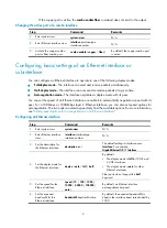
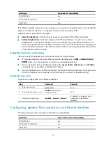
To avoid dropping packets on a link, you can enable generic flow control at both ends of the link. When 

traffic congestion occurs at the receiving end, the receiving end sends a flow control (Pause) frame to ask 
the sending end to suspend sending packets. Generic flow control includes the following types: 


TxRx-mode generic flow control

—Enabled by using the 

flow-control

 command. With TxRx-mode 

generic flow control enabled, an interface can both send and receive flow control frames:  

{


When congestion occurs, the interface sends a flow control frame to its peer.  

{


When the interface receives a flow control frame from its peer, it suspends sending packets to 
its peer. 


Rx-mode generic flow control

—Enabled by using the 

flow-control receive enable

 command. With 

Rx-mode generic flow control enabled, an interface can receive flow control frames, but it cannot 

send flow control frames:  

{


When congestion occurs, the interface cannot send flow control frames to its peer.  

{


When the interface receives a flow control frame from its peer, it suspends sending packets to 
its peer.  

To handle unidirectional traffic congestion on a link, configure the 

flow-control receive enable

 command 

at one end and the 

flow-control

 command at the other end. To enable both ends of a link to handle traffic 

congestion, configure the 

flow-control

 command at both ends.  

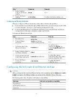
To enable generic flow control on an Ethernet interface: 


Step Command 

Remarks 

1.


Enter system view. 

system-view 

N/A 

2.


Enter Ethernet interface 
view. 

interface

 interface-type 

interface-number


N/A 

3.


Enable generic flow control. 


Enable TxRx-mode generic 
flow control:


flow-control 


Enable Rx-mode generic flow 

control:


flow-control receive enable 

By default, generic flow control is 
disabled on an Ethernet interface.  


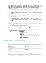
Setting the statistics polling interval 

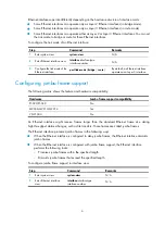
The following matrix shows the supported views of firewall devices for the feature: 


Hardware Supported views 

F5020/F5040 

Ethernet interface view 

M9006/M9010/M9014 

Ethernet interface view 

VFW1000 System 

view 


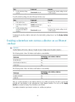
To set the statistics polling interval in system view: 


Step Command 

Remarks 

1.


Enter system view. 

system-view 

N/A 

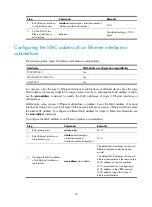
Summary of Contents for SecPath F5020

Page 1: ...figuration Guide Comware V7 Hangzhou H3C Technologies Co Ltd http www h3c com Software version F5020 F5040 firewalls ESS9304 M9006 M9010 M9014 security gateways ESS9114 VFW1000 virtual firewalls ESS92...

Page 2: ...ne SecPath SecCenter SecBlade Comware ITCMM and HUASAN are trademarks of Hangzhou H3C Technologies Co Ltd All other trademarks that may be mentioned in this manual are the property of their respective...

Page 3: ...rewall documentation set Obtaining documentation Technical support Documentation feedback Applicable devices This document applies to the following firewall devices Product series Model Device type H3...

Page 4: ...ional syntax choices separated by vertical bars from which you select one choice multiple choices or none 1 n The argument or keyword and argument combination before the ampersand sign can be entered...

Page 5: ...udes Category Documents Purposes Product description and specifications Marketing brochures Describe product specifications and benefits Hardware specifications and installation Compliance and safety...

Page 6: ...tallation software upgrading and software feature configuration and maintenance documentation Products Solutions Provides information about products and technologies as well as solutions Software Down...

Page 7: ...Ethernet interface 12 Forcibly bringing up a fiber port 13 Configuring a Layer 2 Ethernet interface 15 Setting speed options for autonegotiation on an Ethernet interface 15 Configuring storm suppressi...

Page 8: ...interface range The more interfaces in an interface range the longer the command execution time The maximum number of interface range names is limited only by the system resources To guarantee bulk in...

Page 9: ...s name rather than the interface range to enter the interface range view 3 Optional Display commands available for the first interface in the interface range Enter a question mark at the interface ran...

Page 10: ...faces see Configuring a Layer 2 Ethernet interface For more information about the settings specific to Layer 3 Ethernet interfaces or subinterfaces see Configuring a Layer 3 Ethernet interface or subi...

Page 11: ...Mbps Layer 2 Ethernet interface you can also set speed options for autonegotiation The two ends can select a speed only from the available options For more information see Setting speed options for a...

Page 12: ...e interface type interface number subnumber N A 3 Set the description for the Ethernet subinterface description text The default setting is interface name Interface For example GigabitEthernet1 0 1 1...

Page 13: ...e Configuring jumbo frame support The following matrix shows the feature and hardware compatibility Hardware Jumbo frame support compatibility F5020 F5040 No M9006 M9010 M9014 Yes VFW1000 No An Ethern...

Page 14: ...f the change for guiding packet forwarding Automatically generates traps and logs to inform users to take the correct actions To prevent frequent physical link flapping from affecting system performan...

Page 15: ...the interface flaps the penalty increases by 1000 for each down event It does not increase for up events Ceiling The penalty stops increasing when it reaches the ceiling Suppress limit The accumulated...

Page 16: ...per layer protocols Do not enable the dampening function on an interface with MSTP enabled Configuration procedure To configure dampening on an Ethernet interface Step Command Remarks 1 Enter system v...

Page 17: ...opback tests follow these restrictions and guidelines On an administratively shut down Ethernet interface displayed as in ADM or Administratively DOWN state you cannot perform an internal or external...

Page 18: ...its peer When the interface receives a flow control frame from its peer it suspends sending packets to its peer To handle unidirectional traffic congestion on a link configure the flow control receive...

Page 19: ...rate statistics collection on an Ethernet interface CAUTION Use this feature with caution because it might consume a large amount of system resources The following matrix shows the feature and hardwar...

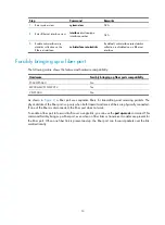
Page 20: ...ports compatibility F5020 F5040 No M9006 M9010 M9014 Yes VFW1000 No As shown in Figure 2 a fiber port uses separate fibers for transmitting and receiving packets The physical state of the fiber port...

Page 21: ...installed with a fiber to copper converter 100 1000 Mbps transceiver module or 100 Mbps transceiver module To solve the problem use the undo port up mode command on the fiber port Configuration proced...

Page 22: ...9010 M9014 Yes VFW1000 No By default speed autonegotiation enables an Ethernet interface to negotiate with its peer for the highest speed that both ends support You can narrow down the speed option li...

Page 23: ...below this threshold Any of the storm constrain broadcast suppression multicast suppression and unicast suppression commands can suppress storm on an interface The broadcast suppression multicast sup...

Page 24: ...s not automatically come up To bring up the interface use the undo shutdown command or disable the storm control function You can configure an Ethernet interface to output threshold event traps and lo...

Page 25: ...thernet interface sends traps when monitored traffic exceeds the upper threshold or drops below the lower threshold from the upper threshold Setting the MDIX mode of an Ethernet interface IMPORTANT Fi...

Page 26: ...nection of an Ethernet interface and displays cable test result within 5 seconds The test result includes the cable s status and some physical parameters If any fault is detected the test result shows...

Page 27: ...s Additionally when a Layer 3 Ethernet subinterface is created it uses the MAC address of its main interface by default As a result all Layer 3 Ethernet subinterfaces of a Layer 3 Ethernet interface s...

Page 28: ...trol on the specified interfaces display storm constrain broadcast multicast unicast interface interface type interface number Display the Ethernet module statistics display ethernet statistics Displa...

Page 29: ...te from the loopback interface to the peer is reachable by performing routing configuration All data packets sent to the loopback interface are considered packets sent to the device itself so the devi...

Page 30: ...setting is NULL0 Interface 4 Restore the default settings for the null interface default N A Configuring an inloopback interface An inloopback interface is a virtual interface created by the system wh...

Page 31: ...nterfaces together to form a Blade aggregation group The corresponding logical interface of a Blade aggregation group is called a Blade aggregate interface For more information see Layer 2 LAN Switchi...

Page 32: ...e 22 Configuring a null interface 23 Configuring an inloopback interface 23 Configuring common Ethernet interface settings 3 D Displaying and maintaining a Blade interface 24 Displaying and maintainin...

Reviews: