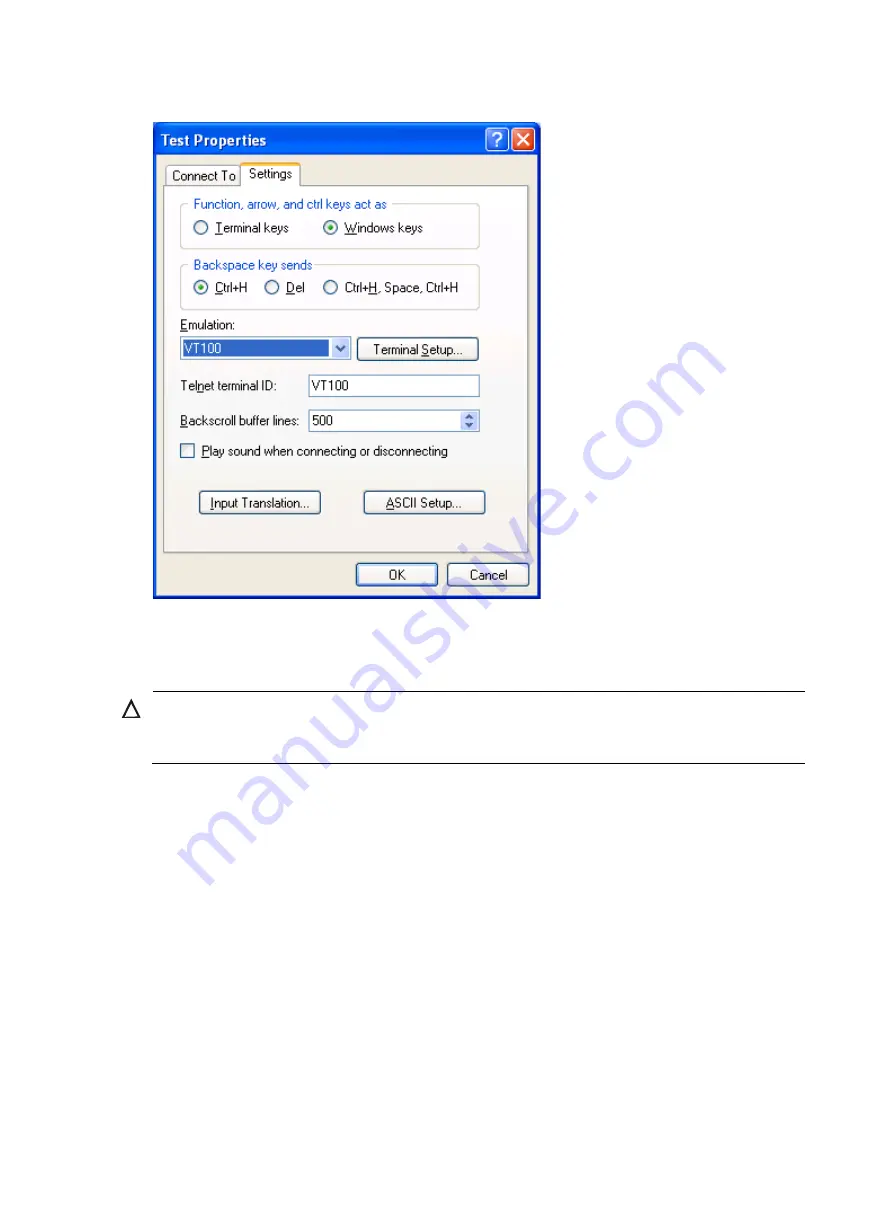
background image


Figure 7


Setting the terminal emulation in Test Properties dialog box 


Powering on the switch 


CAUTION: 

Before powering on the switch, identify the power switch in the equipment room so that you can disconnect
the power supply promptly in case of an emergency. 


Before powering on the switch, verify that: 


The interface cables, power cables and the grounding cable are correctly connected.  


The input power voltage meets the requirement of the switch. 


The console cable is properly connected, the terminal or PC used for configuration has started, and 
the configuration parameters have been set. 

Powering on the switch 

1.


Turn on the power switch of the power source providing power to the switch. 

2.


Turn on the power switch on the switch. 

Before the switch is powered on, the following information is displayed: 

DDR2 SDRAM test successful. 

System is starting... 

Booting Normal Extend BootWare 

The Extend BootWare is self-decompressing.......................... 

Summary of Contents for S9500E Series

Page 1: ...a configuration environment 2 Powering on the switch 5 Powering on the switch 5 Verification after power on 7 Connecting the switch to the network 8 Connecting the switch to the network through an AUX...

Page 2: ...ower distribution rack lightning protection box and connector strip etc of the exchange office Long cables can be bound with cable ties Do not bind cables at the air exhaust vent to prevent the cables...

Page 3: ...nnector of the console cable to the serial port of a PC or terminal 2 Connect the RJ 45 connector of the console cable to the console port of the MPU of the switch NOTE When you remove the console cab...

Page 4: ...serial port to be used from the Connect using list and click OK Figure 4 Setting the serial port used by the HyperTerminal connection 4 Set Bits per second to 9600 Data bits to 8 Parity to None Stop b...

Page 5: ...port parameters 5 Select File Properties in the HyperTerminal window Figure 6 HyperTerminal window 6 On the Settings tab set the emulation to VT100 and click OK NOTE H3C recommends that you select th...

Page 6: ...are correctly connected The input power voltage meets the requirement of the switch The console cable is properly connected the terminal or PC used for configuration has started and the configuration...

Page 7: ...layed at the console terminal Board self testing Board steady testing PASS Board SlotNo 0 Subcard exist testing PASS DX246 testing PASS PHY88E1111 testing PASS CPLD1 testing PASS CPLD2 testing PASS NS...

Page 8: ...at the prompt H3C NOTE The S9500E switches provide a command line interface CLI For more information about the CLI see H3C S9500E Switch Series Fundamentals Configuration Guide The output depends on y...

Page 9: ...male connector Plug the RJ 45 connector into the AUX port of the switch and the DB 9 male connector into the DB 9 female port of the modem An AUX cable is the same as a console cable For more informa...

Page 10: ...ng a fiber network facility make sure the type of the connector and the fiber matches the adopted optical port Be sure to install the dust cover if the optical port is not connected to a fiber connect...

Page 11: ...t makes good skin contact and is well grounded 2 Remove the protective cap from the fiber connector and use dust free paper and absolute alcohol to clean the end face of the fiber connector 3 Connect...

Page 12: ...tray optional NOTE The installation method described below is based on an N68 rack The installation procedure is only for your reference if you use a non N68 rack A fiber management tray FMT is insta...

Page 13: ...12 Figure 12 Installing FMTs...

Reviews: