


Quick Start
H3C S5500-EI Series Ethernet Switches
Chapter 1 Product Overview
1-35
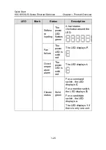
Table 1-9
Description of the LED for each extended module slot
LED
Mark
Status
Description
Gree
n
The port connection is
normal. The LED
flashes at a high
frequency when the
port is sending or
receiving data.
LED for
extended
module slot
—
This
LED is
not
affected
by the
Mode
button.
OFF
The port is not
connected.
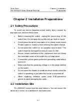
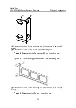
1.11 CX4 Cable
You can use a CX4 cable to connect the CX4 port on the rear
panel of the S5500-EI series to another CX4 port.
Figure 1-1
CX4 cable
The following three types of CX4 cables are available:
z
50 cm (19.7 in.): The connectors at both ends of the cable
are bayonet connectors.
z
100 cm (39.4 in.): The connectors at both ends of the cable
are bayonet connectors.
z
300 cm (118.1 in.): The connectors at both ends of the cable
are bayonet connectors.


