background image


32 

Appendix A Chassis views and technical 
specifications 

Chassis views 

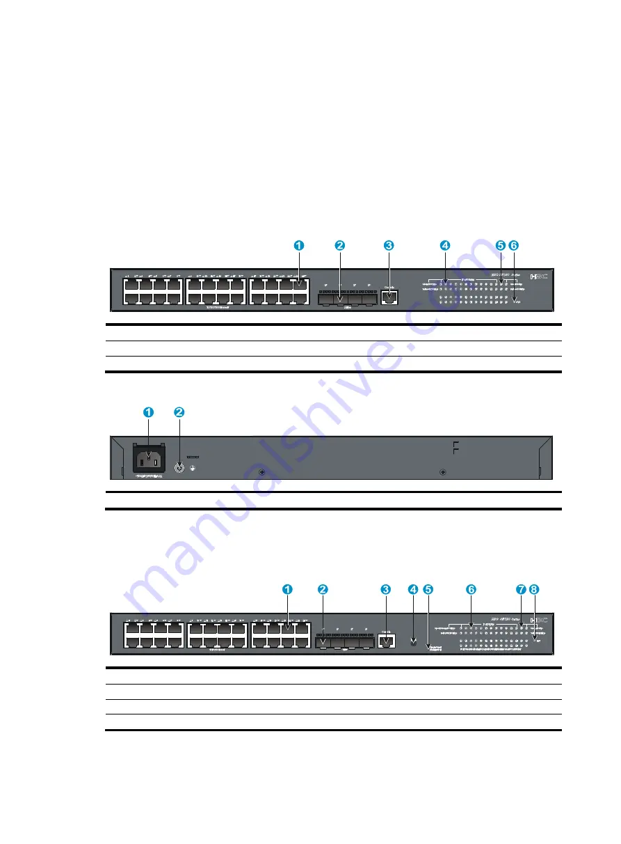
S5130-28S-EI 

Figure 35 Front panel 


(1) 10/100/1000Base-T autosensing Ethernet port

(2) SFP+ port 

(3) Console port 

(4) 10/100/1000Base-T autosensing Ethernet port LED

(5) SFP+ port LED 

(6) System status LED (SYS) 


Figure 36 Rear panel 


(1) AC-input power receptacle 

(2) Grounding screw 


S5130-28S-PWR-EI 

Figure 37 Front panel 


(1) 10/100/1000Base-T autosensing Ethernet port

(2) SFP+ port  

(3) Console port  

(4) Port LED mode switching button 

(5) Port mode LED 

(6) 10/100/1000Base-T autosensing Ethernet port LED

(7) SFP+ port LED  

(8) System status LED (SYS) 


Summary of Contents for S5130-EI Series

Page 1: ...H3C S5130 EI Switch Series Installation Guide New H3C Technologies Co Ltd http www h3c com Document version 6W106 20190409...

Page 2: ...respective owners Notice The information in this document is subject to change without notice All contents in this document including statements information and recommendations are believed to be acc...

Page 3: ...syntax choices keywords or arguments that are optional x y Braces enclose a set of required syntax choices separated by vertical bars from which you select one x y Square brackets enclose a set of opt...

Page 4: ...s a Layer 2 or Layer 3 switch or a router that supports Layer 2 forwarding and other Layer 2 features Represents an access controller a unified wired WLAN module or the access controller engine on a u...

Page 5: ...Documentation feedback You can e mail your comments about product documentation to info h3c com We appreciate your comments...

Page 6: ...Connecting a DC power cord for the built in DC power module other switch models than S5130 28PS EI 16 Verifying the installation 17 Accessing the switch for the first time 18 Setting up the configura...

Page 7: ...ical specifications 39 Appendix B FRUs 44 Appendix C Ports and LEDs 45 Ports 45 Console port 45 SFP port 45 SFP port 48 10 100 1000Base T autosensing Ethernet port 48 1 10GBase T autosensing Ethernet...

Page 8: ...tilation at the installation site and keep the air inlet and outlet vents of the switch free of obstruction Connect the yellow green protection grounding cable before power on Make sure the power sour...

Page 9: ...e humidity is low In the worst case electrostatic adsorption can cause communication failure Table 1 Dust concentration limit in the equipment room Substance Concentration limit particles m Dust 3 x 1...

Page 10: ...vent signal ports from getting damaged by over voltage or over current caused by lightning strikes only route interface cables indoors Laser safety WARNING Do not stare into any fiber port when the sw...

Page 11: ...shall not be liable for any consequence Figure 1 Hardware installation flow Installing the switch in a 19 inch rack Mounting brackets Table 3 describes the mounting brackets provided with the switch...

Page 12: ...racket to the rack post Attaching the mounting brackets to the switch The switch provides two installation positions for mounting brackets one front mounting position near the network ports and one re...

Page 13: ...ure 5 Attaching a two hole mounting bracket to the rear mounting position on an S5130 28S EI switch Figure 6 Attaching a four hole mounting bracket to the front mounting position on an S5130 28F EI sw...

Page 14: ...person attaches the mounting brackets with M6 screws user supplied to the rack Figure 8 Mounting an S5130 28F EI switch by the front mounting position Figure 9 Mounting an S5130 28F EI switch by the...

Page 15: ...a grounding conductor buried in the earth ground NOTE To guarantee the grounding effect use the grounding cable provided with the switch to connect to the grounding strip in the equipment room as long...

Page 16: ...ion sheath by using a wire stripper c Use the needle nose pliers to bend the bare wire d Hook the grounding cable to the post on the grounding strip and use the hex nut to secure the cable to the post...

Page 17: ...and make sure the circuit breaker is off before installation The S5130 28F EI switch provides two power module slots and comes with power module slot 1 empty and a filler panel in power module slot 2...

Page 18: ...he power module tilts while inserting the power module pull out the power module realign it with the slot and then insert it again 5 Fasten the captive screws on the power module with a Phillips screw...

Page 19: ...r source PSR150 D1 48 VDC power source in the equipment room or an RPS RPS800 A or RPS1600 A Connecting the power cord for a PSR150 D1 power module S5130 28S EI S5130 28S PWR EI S5130 28TP EI AC power...

Page 20: ...er cord for a PSR150 A1 power module To connect the power cord for an AC power module 1 Pull the bail latch leftward as shown in Figure 18 2 Connect the female connector of the AC power cord to the po...

Page 21: ...To connect the power cord for a PSR150 D1 module 1 Correctly orient the connector of the power cord and align it with the power receptacle on the power module and insert the connector into the power...

Page 22: ...remove the cover as shown in Figure 21 Keep the removed cover secure Reinstall the cover if you will not use the RPS receptacle 2 Correctly orient the RPS power cord connector and insert the connecto...

Page 23: ...witch requires a DC power cord with a JD5 connector To connect a DC power cord to a 48 VDC power source identify the positive and negative marks on the two wires of the power cord to avoid connection...

Page 24: ...ce for heat dissipation around the switch and the rack or workbench is stable The grounding cable is securely connected The correct power source is used The power cords are correctly connected All the...

Page 25: ...the switch Prepare yourself or purchase it from H3C Figure 24 Connecting the serial console port to a PC Connecting the console cable A console cable is an 8 core shielded cable with a crimped RJ 45 c...

Page 26: ...ng switch first disconnect the switch end Connecting the mini USB console cable S5130 28PS EI switch 1 Connect the standard USB connector to the USB port of the PC or configuration terminal 2 Connect...

Page 27: ...20 Figure 26 Device Driver Installation Wizard 6 Click Continue Anyway if the following dialog box appears Figure 27 Software Installation 7 Click Finish...

Page 28: ...user guides for these programs The following are the required terminal settings Bits per second 9 600 Data bits 8 Stop bits 1 Parity None Flow control None Starting the switch NOTE In the BootROM men...

Page 29: ...nt The Boot ROM interface and menu options vary by software version For more information about Boot ROM menu options see the software matching release notes for the device From the Boot ROM menu you c...

Page 30: ...eability IRF fabric setup flowchart Figure 29 IRF fabric setup flowchart To set up an IRF fabric Step Description 1 Plan IRF fabric setup Plan the installation site and IRF fabric setup parameters Pla...

Page 31: ...the installation site depending on your network solution as follows Place all IRF member switches in one rack for centralized high density access Distribute the IRF member switches in different racks...

Page 32: ...idth and availability Figure 30 and Figure 31 show the topologies of an IRF fabric made up of three S5130 28S EI switches The IRF port connections in the two figures are for illustration only and more...

Page 33: ...topology Connecting the IRF member switches in one rack Use SFP DAC cables to connect the IRF member switches 9 switches in this example in a rack as shown in Figure 32 The switches in the ring topol...

Page 34: ...iorities and IRF port bindings Follow these guidelines when you configure the switches Assign the master switch higher member priority than any other switch Bind physical ports to IRF port 1 on one sw...

Page 35: ...y that you can manage all member switches as if they were one node 5 Display the running status of the IRF fabric by using the commands in Table 6 Table 6 Displaying and maintaining IRF configuration...

Page 36: ...description LED Mark Status Description System status LED SYS Off The switch is powered off RPS status LED RPS Steady green The AC input is normal and the RPS is in position or working normally Steady...

Page 37: ...atus LED is on but the RPS status LED is steady yellow an AC input failure has occurred To resolve the problem a Verify that the AC power cord is securely connected to the switch and the AC input powe...

Page 38: ...4 Verify that the following settings are configured for the terminal Baud rate 9600 Data bits 8 Parity None Stop bits 1 Flow control None 5 Verify that the console cable is not faulty 6 If the proble...

Page 39: ...Base T autosensing Ethernet port LED 5 SFP port LED 6 System status LED SYS Figure 36 Rear panel 1 AC input power receptacle 2 Grounding screw S5130 28S PWR EI Figure 37 Front panel 1 10 100 1000Base...

Page 40: ...10 100 1000Base T autosensing Ethernet port 2 SFP port 3 Console port 4 Port LED mode switching button 5 Port mode LED 6 10 100 1000Base T autosensing Ethernet port LED 7 SFP port LED 8 System status...

Page 41: ...autosensing Ethernet port LED Figure 42 Rear panel 1 AC input power receptacle 2 Grounding screw S5130 28TP PWR EI Figure 43 Front panel 1 10 100 1000Base T autosensing Ethernet port 2 SFP port 3 1 10...

Page 42: ...45 Front panel 1 10 100 1000Base T autosensing Ethernet port 2 10 100 1000Base T autosensing Ethernet port LED 3 Console port 4 SFP port LED 5 SFP port 6 System status LED SYS 7 RPS status LED RPS Fig...

Page 43: ...LED SYS 8 RPS status LED RPS 9 SFP port LED Figure 48 Rear panel 1 Grounding screw 2 AC input power receptacle 3 RPS receptacle S5130 52TP EI Figure 49 Front panel 1 10 100 1000Base T autosensing Ethe...

Page 44: ...port 2 10 100 1000Base T autosensing Ethernet port LED 3 SFP port 4 Console port 5 Port LED mode switching button 6 Port mode LED 7 System status LED SYS 8 RPS status LED RPS 9 1 10GBase T autosensin...

Page 45: ...er module 2 status LED PWR2 Figure 54 Rear panel 1 Grounding screw 2 Power module slot 1 3 Power module slot 2 The S5130 28F EI switch comes with no power module or filler panel in power module slot 1...

Page 46: ...nput power receptacle Technical specifications Table 8 Technical specifications for non PoE switch models 1 Item S5130 52S EI S5130 28F EI S5130 52TP EI Dimensions H W D 43 6 440 260 mm 1 72 17 32 10...

Page 47: ...as shown in Table 11 AC power source Rated voltage 100 VAC to 240 VAC 50 or 60 Hz Max voltage 90 VAC to 264 VAC 47 to 63 Hz DC power source 48 VDC power source in the equipment room or an RPS recommen...

Page 48: ...corresponding SFP ports form combo interfaces 1 10GBase T autosensing Ethernet ports N A 2 N A 100 1000Bas e X SFP ports N A N A 8 Each and its 10 100 1000Base T autosensing Ethernet port form a comb...

Page 49: ...17 64 lb 8 kg 17 64 lb 7 kg 15 43 lb Console ports One serial console port One serial console port One serial console port One serial console port One serial console port 10 100 1000 Base T autosensin...

Page 50: ...PoE consumptio n AC 490 W including 370 W PoE consumpti on DC 890 W including 800 W PoE consumpti on AC 470 W including 370 W PoE consumptio n DC 910 W including 800 W PoE consumptio n Chassis leakag...

Page 51: ...to 240 VAC 50 Hz or 60 Hz For more information about the power modules see H3C PSR150 A PSR150 D Series Power Modules User Manual Max input voltage 90 VAC to 264 VAC 47 Hz to 63 Hz High voltage DC inp...

Page 52: ...des connection to the USB port of a local PC running terminal emulation program SFP port The switch provides SFP ports You can install the GE SFP transceiver modules and cables in Table 13 10 GE SFP t...

Page 53: ...P GE LH40 SM155 0 1550 LC Single mode 9 125 N A 40 km 24 86 miles SFP GE LH70 SM155 0 1550 LC Single mode 9 125 N A 70 km 43 50 miles SFP GE LH80 SM155 0 1550 LC Single mode 9 125 N A 80 km 49 71 mile...

Page 54: ...8 27 ft 160 26 m 85 30 ft SFP XG SX M M850 D 850 LC Multi mode 50 125 2000 300 m 984 3 ft 500 82 m 269 03 ft 400 66 m 216 54 ft Multi mode 62 5 125 200 33 m 108 27 ft 160 26 m 85 30 ft SFP XG LX S M13...

Page 55: ...er diameter m Max transmission distance SFP FE SX MM1310 A 1310 LC Multi mode 50 125 2 km 1 24 miles Multi mode 62 5 125 SFP FE LX SM1310 A 1310 LC Single mode 9 125 15 km 9 32 miles SFP FE LX SM1310...

Page 56: ...power cords and twisted pair cables at and around the distribution frame For ports adjacent to one another on the device the peer ports on the distribution frame is preferably not adjacent for example...

Page 57: ...y red A power module is installed in the power module slot but the power module is faulty Off No power module is installed in the power module slot RPS status LED The S5130 28S HPWR EI S5130 28PS EI S...

Page 58: ...or receiving data at 100 Mbps Flashing yellow 3 Hz The port has failed POST Off No transceiver module is installed in the port or no link is present on the port SFP port status LED The S5130 28F EI S...

Page 59: ...No transceiver module is installed in the port or no 1 Gbps link is present on the port The port mode LED is operating in PoE mode applicable to the PoE switch models 10 100 1000Base T autosensing Et...

Page 60: ...or the port is experiencing a PoE failure Flashing yellow 3 Hz The port has failed POST Off The port is not supplying PoE The S5130 28S EI S5130 28TP EI S5130 28S PWR EI S5130 28TP PWR EI and S5130 2...

Page 61: ...port PoE capacity The port fails to meet the power requirement of the PD because of power insufficiency of the switch Off The port is not supplying PoE power Yellow LED Steady on A non PD device is a...

Page 62: ...s and a link is present on the port Flashing The port is sending or receiving data at 1 Gbps Flashing 3 Hz The port has failed POST Off No 1 Gbps link is present on the port The port mode LED is opera...

Page 63: ...56 Figure 58 Airflow through the chassis 1 Air inlet side 2 Air outlet side 3 Port side 1 2 3...

Reviews: