


Operation Manual – MSTP
H3C S3100-52P Ethernet Switch
Chapter 1 MSTP Configuration
1-56
1.12 Displaying and Maintaining MSTP
To do...
Use the command...
Remarks
Display the state and statistics
information about spanning
trees of the current device
display stp
[
instance
instance-id
]
[
interface
interface-list
|
slot
slot-number
]
[
brief
]
Display region configuration
display stp
region-configuration
Display information about the
ports that are shut down by
STP protection
display stp portdown
Display information about the
ports that are blocked by STP
protection
display stp abnormalport
Display information about the
root port of the instance where
the switch reside
display stp root
Available in
any view
Clear statistics about MSTP
reset stp
[
interface
interface-list
]
Available in
user view
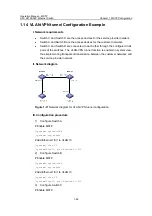
1.13 MSTP Configuration Example
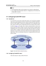
I. Network requirements
Implement MSTP in the network shown in
to enable packets of different
VLANs to be forwarded along different MSTIs. The detailed configurations are as
follows:
z
All switches in the network belong to the same MST region.
z
Packets of VLAN 10, VLAN 30, VLAN 40, and VLAN 20 are forwarded along MSTI
1, MSTI 3, MSTI 4, and MSTI 0 respectively.
In this network, Switch A and Switch B operate on the convergence layer; Switch C and
Switch D operate on the access layer. VLAN 10 and VLAN 30 are limited in the
convergence layer and VLAN 40 is limited in the access layer. Switch A and Switch B
are configured as the root bridges of MSTI 1 and MSTI 3 respectively. Switch C is
configured as the root bridge of MSTI 4.


