


48
Figure 47
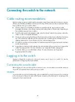
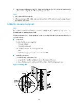
Installing the protection cover
Verifying the installation
WARNING!
An S12504 has one power switch, an S12508 has one power switch, and an S12518 has two power
switches. Make sure you have turned off the power before checking the installation to avoid bodily injury
and switch damage.
After the installation is completed, verify the installation against the following list. Be sure that all check
results are positive.
Table 13
Installation checklist
Item
Result
Remarks
Yes
No
The grounding cable is correctly grounded.
Fan trays are correctly installed and make close contact with the
backplane.
Power supplies are correctly installed and have close contact with
the frames.
The power switch is off (the power switch is at the OFF position).
Power cords are correctly connected.
MPUs are correctly installed and have close contact with the
backplane.
LPUs are correctly installed and have close contact with the
backplane.
Switching fabric modules are correctly installed and have close
contact with the backplane.
Summary of Contents for S12500 Series
Page 40: ...30 Figure 28 Installing an upper expansion cable management bracket 1 2 3 4 5 6 7...
Page 109: ...99 Figure 74 Replacing a card for the S12504 A Card to be removed B Card to be installed...
Page 149: ...139 Figure 85 Loopback operation on an optical transceiver...
Page 164: ...154 Figure 100 Example of a device label...


