


45
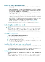
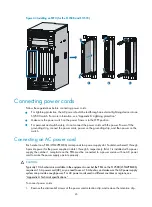
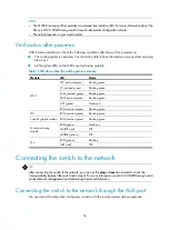
Figure 44
Installing an MPU (for the S12508 and S12518)
Connecting power cords
Follow these guidelines before connecting power cords:
•
For lightning protection, the AC power should be led through an external lightning device into an
S12500 switch. For more information, see "Appendix D Lightning protection."
•
Make sure the power switch on the power frame is in the OFF position.
•
For personal and switch safety, do not connect the power cords with the power. Power off the
grounding strip, connect the power cords, power on the grounding strip, and then power on the
switch.
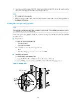
Connecting an AC power cord
Each socket on a PEM (LSTM2PEMC6) corresponds to a power supply slot. Sockets numbered 1 through
6 provide power for the power supplies in slots 1 through 6, respectively. If slot 1 is installed with a power
supply, the number 1 receptacle on the PEM must be connected to a power source with an AC power
cord to make the power supply operate properly.
CAUTION:
Typically 10 A busbars are available in the equipment room but the PEM on the S12500 (LSTM2PEMC6)
requires a 16 A power cord (AC), so you need to use a 16 A busbar, and make sure the AC power supply
system can provide enough power. For AC power cords used in different countries or regions, see
"Appendix A Technical specifications."
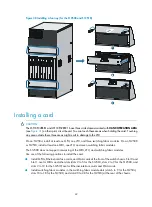
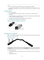
To connect power cords:
1.
Remove the strain-relief screws of the power cord retention clip, and remove the retention clip.
1
2
3
Summary of Contents for S12500 Series
Page 40: ...30 Figure 28 Installing an upper expansion cable management bracket 1 2 3 4 5 6 7...
Page 109: ...99 Figure 74 Replacing a card for the S12504 A Card to be removed B Card to be installed...
Page 149: ...139 Figure 85 Loopback operation on an optical transceiver...
Page 164: ...154 Figure 100 Example of a device label...


