


2-17
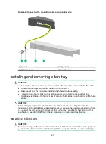
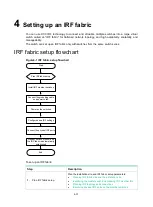
Figure2-20 Connecting the grounding cable to a grounding strip
(1) Hex nut
(2) Ring terminal
(3) Grounding post
(4) Grounding strip
Installing and removing a fan tray
CAUTION:
•
For adequate heat dissipation, you must install five fan trays of the same model for the switch.
•
Do not install fan trays of different models on the same switch.
•
Make sure all slots have a module installed when the switch is operating.
•
If more than one fan tray fails during switch operation, do not remove the failed fan trays
simultaneously. Replace the fan trays one by one and finish replacing each fan tray within three
minutes.
CAUTION:
Select fan trays and power supplies that have the airflow direction matching the ventilation
requirements at the installation site. As a best practice, make sure the power supplies and fan trays
on the switch have the same airflow direction. For the fan trays available for the switch and their
specifications, see
H3C S6825 Switch Series Hardware Information and Specifications
.
Installing a fan tray
CAUTION:
To prevent damage to the fan tray or the connectors on the backplane, insert the fan tray gently. If
you encounter a hard resistance while inserting the fan tray, pull out the fan tray and insert it again.