background image

Erweiterung des KVM-Matrixsystems

G&D ControlCenter-Compact · 

15

Deutsch

Erweiterung des KVM-Matrixsystems

Falls die Anzahl der Ports eines Matrixswitches für den gewünschten Einsatzzweck 

nicht ausreicht, können Sie mehrere Matrixswitches zu einem Verbund zusammen-

fügen. Hierfür stehen folgende Technologien zur Verfügung:

Kaskadierung (Standard)

Für den Aufbau einer Kaskade schließen Sie an den Master-Matrixswitch einen 

Slave-Matrixswitch an. An den Slave-Matrixswitch können Sie wahlweise Target-

Computer oder weitere Slave-Matrixswitches (max. zwei Kaskadenstufen) anschlie-

ßen.

Aufgrund der Top-Down-Struktur der Kaskade können Arbeitsplatzmodule nur solche 

Target-Computer aufschalten, die an denselben Matrixswitch, wie das Arbeitsplatzmo-

dul, oder an einen in der Baumstruktur untergeordneten (kaskadierten) Matrixswitch 

angeschlossen sind.

Weitere Informationen zur 

Kaskadierung

 finden Sie auf den folgenden Seiten.

KVM Matrix-Grid™ (kostenpflichtig)

Die Freischalt-Funktion 

KVM Matrix-Grid™

 erlaubt die flexible Nutzung jedes Matrix-

switch-Ports innerhalb des Matrix-Grids für Arbeitsplatzmodule, Target-Module 

oder Grid-Lines (s. u.). Während in der Kaskade nur die Anzahl der anschließbaren 

Target-Computer erweitert wird, erlaubt das Matrix-Grid die universelle Erweiterung 

des bestehenden KVM-Systems.

Zusätzlich hebt die Funktion die Einschränkungen der Top-Down-Struktur inner-

halb der Kaskade auf und ermöglicht die bidirektionale Kommunikation zwischen 

den, an verschiedenen Matrixswitches angeschlossenen, Arbeitsplatz- und Target-

Modulen. Hierdurch können Sie mehrere digitale Matrixswitches zu einem großen 

Matrix-Verbund kombinieren. Die Arbeitsplatzmodule und Target-Computer kön-

nen Sie an beliebige Matrixswitches innerhalb des Matrix-Grids anschließen.

Alle Arbeitsplatzmodule können auf jeden beliebigen Target-Computer (unabhän-

gig vom Matrixswitch, an den sie angeschlossen sind) aufgeschaltet werden.

Das System übernimmt das (bidirektionale) Routing der KVM-Signale und wählt 

hierbei den jeweils optimalen Signalpfad zwischen den Modulen.

Weitere Informationen zum 

KVM Matrix-Grid™

 finden Sie im separaten Addendum.

Summary of Contents for ControlCenter-Compact-16C

Page 1: ...Guntermann Drunck GmbH www gdsys de ControlCenter Compact A9100282 1 00 Installation und Bedienung DE EN Installation and Operation...

Page 2: ...s G D bernimmt keine Gew hrleistung f r Ger te die nicht bestimmungsgem eingesetzt wurden nicht autorisiert repariert oder modifiziert wurden schwere u ere Besch digungen aufweisen welche nicht bei Li...

Page 3: ...gen 9 Konfiguration der Netzwerkschnittstellen 9 Konfiguration der globalen Netzwerkeinstellungen 10 Verwendung des Reset Tasters 11 Wiederherstellung der Standardeinstellungen 11 Tempor re Deaktivier...

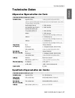
Page 4: ...Compact Erweiterung durch Stacking 23 Anschluss eines Stack Matrixswitches 23 Bus Adresse eines Matrixswitches einstellen 24 Statusanzeigen 25 Technische Daten 27 Allgemeine Eigenschaften der Serie 27...

Page 5: ...ellen Sie vor Installationsarbeiten sicher dass das Ger t spannungsfrei ist Zie hen Sie den Netzstecker oder die Spannungsversorgung am Ger t ab St ndigen Zugang zu den Netzsteckern der Ger te sichers...

Page 6: ...platzes bedienen Sie den aufgeschalteten Computer In der ControlCenter Compact Serie sind folgende Varianten verf gbar An die Dynamic Ports k nnen Sie wahlweise Arbeitsplatz oder Target Module anschli...

Page 7: ...gesteuert Lieferumfang 1 Zentralmodul ControlCenter Compact 2 Stromversorgungskabel PowerCable 2 Standard 1 Rackmount Set 1 Service Kabel USB Service 2 1 Handbuch Installationsanleitung 1 Handbuch Sat...

Page 8: ...ie das Stromversorgungs kabel mit einer Netzsteckdose eines anderen Stromkreises und schalten Sie den Netzschalter ein HINWEIS Die Skizzen zeigen die Variante ControlCenter Compact 32C Die verschie de...

Page 9: ...on Schnittstellen der einzelnen Arbeitsplatzmodule mit jeweils einem Dynamic Port des Zentralmoduls Verwenden Sie hierzu eine Twisted Pair Verkabelung der Kategorie 5e oder h her HINWEIS Die maximale...

Page 10: ...u eine Twisted Pair Verkabelung der Kategorie 5e oder h her WICHTIG Die maximale Distanz zwischen einem Target Modul und dem Zentral modul betr gt 140 Meter Handbuch Artikelnummer Download Link Standa...

Page 11: ...Zentralmoduls ber die Webapplikation Config Panel und der Einsatz der erweiterten Netzwerkfunktionalit ten z B Authentifizierung gegen ber Verzeichnisdiensten Zeitsynchronisation ber einen NTP Server...

Page 12: ...sind f r L ngen ber 80 Metern Kabel der Codierung AWG24 oder besser zu verwenden Die folgenden Kabel haben w hrend des Testbetriebs unter Laborbedingungen die besten Ergebnisse erzielt HINWEIS Das Ver...

Page 13: ...die Eingabetaste um die Anmeldung durchzuf hren und das On Screen Display zu ffnen 3 Bet tigen Sie die F11 Taste zum Aufruf des Configuration Men s 4 W hlen Sie die Zeile Network und bet tigen Sie di...

Page 14: ...8 Taste zur Auswahl des Betriebsmodus der Schnittstelle Network A bzw Network B Off Netzwerkschnittstelle ausschalten Static Es wird eine statische IP Adresse zugeteilt DHCP Bezug der IP Adresse von e...

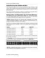
Page 15: ...moduls wieder her 1 Schalten Sie ggf beide Netzteile des Zentralmodules aus 2 Bet tigen Sie den Reset Taster an der Frontseite des Ger tes und halten Sie diesen gedr ckt 3 Halten Sie den Taster weiter...

Page 16: ...Netzfilterregeln den Zugang auf die Webappli kation k nnen Sie die Netzfilterregeln tempor r deaktivieren um diese anschlie end zu editieren So deaktivieren Sie die eingerichteten Netzfilterregeln tem...

Page 17: ...onfigurierten Ports an An die Up Ports werden bergeordnete Matrixswitches angeschlossen An die Down Ports werden untergeordnete Matrixswitches angeschlossen Die Ports der verschiedenen Ger tevarianten...

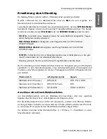
Page 18: ...32C 1 bis 8 9 bis 32 ControlCenter Compact 48C 1 bis 12 13 bis 48 ControlCenter Compact 64C 1 bis 16 17 bis 64 ControlCenter Compact 80C 1 bis 20 21 bis 80 HINWEIS Der Kompatibilit tsmodus wurde in d...

Page 19: ...alt Funktion KVM Matrix Grid erlaubt die flexible Nutzung jedes Matrix switch Ports innerhalb des Matrix Grids f r Arbeitsplatzmodule Target Module oder Grid Lines s u W hrend in der Kaskade nur die A...

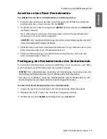
Page 20: ...von ber bzw untergeordneten Matrixswitches konfiguriert Der folgende Screenshot der Webapplikation Config Panel stellt die Standardauftei lung der Ports visuell dar An die Up Ports k nnen Sie die ber...

Page 21: ...adenmodus des Master und oder des Slave Zentralmoduls s Seite 17 Festlegung des Kaskadenmodus des Zentralmoduls Die einzelnen Zentralmodule erkennen selbst ndig ob sie als Master oder Slave Ger t inne...

Page 22: ...eitet Master In diesem Betriebsmodus k nnen an Dynamic Ports die f r den Anschluss von Target Modulen konfiguriert sind ausschlie lich Arbeitsplatzmodule angeschlossen werden Das Editieren der Bezeich...

Page 23: ...ax sieben zus tzliche Videokan le und einen USB 2 0 RS 232 Kanal zuordnen Dem KVM Kanal eines Rechners k nnen Sie ebenfalls max sieben zus tzliche Video kan le zuordnen Hinzu kommt ein Pool aus vier G...

Page 24: ...Module des Matrixswitches aufgelistet die Sie der neuen Kanal Gruppierung hinzuf gen k nnen 4 Klicken Sie in der linken Spalte Nicht zugeordnet auf das hinzuzuf gende Modul und in der rechten Spalte Z...

Page 25: ...rung weitere Module hinzu oder entfernen Sie Module aus der Konfiguration HINWEIS Die in der Kanal Gruppierung enthaltenen Arbeitsplatz oder Rechner module werden in der Auflistung der Module mit eine...

Page 26: ...Sie in der rechten Spalte Zugeordnet auf ein Modul das einem der KVM Kan le 2 bis 8 bzw dem USB RS232 Kanal zugeordnet ist Klicken Sie auf Pfeil links um die Zuordnung des Moduls zu l schen 5 Wiederh...

Page 27: ...ch bezeichnet ber den zus tzliche Signale eines Rechners bzw Arbeitsplatzes bertragen werden Ein Stack Matrixswitch wird nicht vom Anwender sondern vom Primary Matrix switch geschaltet Schaltet der An...

Page 28: ...ern Sie die Bus Adresse eines Matrixswitches 1 Klicken Sie im Strukturbaum auf KVM Matrixsysteme Name Matrixswitches 2 Klicken Sie mit der rechten Maustaste auf den Matrixswitch und anschlie end auf K...

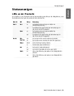
Page 29: ...an Das Netzteil ist eingeschaltet und liefert die erforderliche Spannung aus Das Netzteil ist ausgeschaltet oder die Verbindung mit dem Stromnetz nicht hergestellt Device Port function aus An den Dyna...

Page 30: ...Netzwerkschnittstelle festgestellt Dynamic Port gelb an Status Modus Ein Benutzer ist am Arbeitsplatzmodul eingeloggt bzw auf das Targetmodul aufgeschaltet Port Modus Der Port ist f r den Anschluss ei...

Page 31: ...e Funktionen USB 3 0 1 USB A Buchse reserviert f r zuk nftige Funktionen Hauptstrom versorgung Typ internes Netzteil Anschluss 1 Kaltger testecker IEC 320 C14 Stromaufnahme siehe spezifische Eigenscha...

Page 32: ...0 50Hz 0 8 0 4A Redundante Stromversorgung Stromaufnahme 100 240V 60 50Hz 0 8 0 4A Geh use Dimensionen B H T 435 88 211 mm CONTROLCENTER COMPACT 64C Schnittstellen Dynamic Ports 64 RJ45 Buchse Hauptst...

Page 33: ...Deutsch...

Page 34: ...ill not provide warranty for devices that Are not used as intended Are repaired or modified by unauthorized personnel Show severe external damages that was not reported on the receipt of goods Have be...

Page 35: ...etwork settings 9 Configuring network ports 9 Configuring the global network settings 10 Reset button 11 Resetting the default settings 11 Disabling the netfilter rules temporarily 12 Configuring dyna...

Page 36: ...Compact Expanding the system through stacking 23 Connecting a stack matrix switch 23 Adjusting the bus address of matrix switches 24 Status displays 25 Technical data 27 General features of the series...

Page 37: ...er supply before installation Before installation ensure that the device has been disconnected from the power source Disconnect the main power plug or the power supply of the device Ensure constant ac...

Page 38: ...accessed computer with console keyboard and console mouse The ControlCenter Compact series includes the following variants Use the dynamic ports to connect either user modules or target modules Expan...

Page 39: ...odule Package contents 1 ControlCenter Compact matrix switch 2 power cable PowerCable 2 Standard 1 rack mount set 1 service cable USB Service 2 1 manual Installation Guide 1 manual set Target modules...

Page 40: ...he power cable with a power outlet of another power circuit and turn the power button on NOTE The following drawings refer to the ControlCenter Compact 32C The different variants vary in the number of...

Page 41: ...h individual user module to one of the dynamic ports of the central module Use a category 5e or better twisted pair cabling for connecting the devices IMPORTANT You can place user modules up to 140 me...

Page 42: ...Use a category 5e or better twisted pair cabling for connecting the devices IMPORTANT You can place target modules up to 140 metres away from the central module Manual Order number Download link Stand...

Page 43: ...d to connect the central module to one or two local networks to configure the central module via Config Panel web application and use the enhanced network functionalities for example authentication ag...

Page 44: ...with at least AWG24 coding have to be used for lengths over 80 metres The following cables achieved the best results during test operation NOTE It is permitted to connect several segments of a cable c...

Page 45: ...wing data to the login box 2 Press Enter to login and open the on screen display 3 Press F11 to call the Configuration menu 4 Select the Network entry and press Enter 5 Select the Settings entry and p...

Page 46: ...r Network B Off switches off network interface Static uses static settings DHCP obtains the settings from a DHCP server IP address Enter the interface IP address This setting is auto obtained in the D...

Page 47: ...ettings of the central module 1 Turn off both power packs of the central module 2 Press and hold the Reset button on the front panel of the device 3 Keep the button pressed and turn the device on 4 Re...

Page 48: ...currently adjusted netfilter rules prevent access to the Config Panel web applica tion they can be can temporarily disabled in order to be edited How to disable the netfilter rules temporarily 1 If n...

Page 49: ...connect further matrix switches to the configured ports Connect master matrix switches to up ports Connect slave matrix switches to down ports By deault the ports of the different variants of the Con...

Page 50: ...ontrolCenter Compact 32C 1 to 8 9 to 32 ControlCenter Compact 48C 1 to 12 13 to 48 ControlCenter Compact 64C 1 to 16 17 to 64 ControlCenter Compact 80C 1 to 20 21 to 80 NOTE For matrix switches of the...

Page 51: ...charge The premium function KVM Matrix Grid allows you to use each matrix port within the matrix grid to connect either user modules target modules or grid lines see below While a cascade increases o...

Page 52: ...he ControlCenter Compact series are configured to connect both master and slave matrix switches The following screenshot of the web application Config Panel shows the default port assignment Connect m...

Page 53: ...if necessary change the cascade mode of the master and or the slave central module see page 17 Defining the cascade mode of the central module The central modules detect independently whether they are...

Page 54: ...ave mode Master In this operating mode you can only connect user modules to Dynamic Ports that are configured for the connection of target mod ules You can change the names of the connected target mod...

Page 55: ...nel to the KVM channel of the console You can assign up to seven additional video channels to the KVM channel of the com puter too In addition you can create a pool of four devices for the USB 2 0 RS...

Page 56: ...click on the module you want to add In the right column Assigned click on the channel you want to add the module to 5 Click arrow right to assign the module to the chosen channel 6 Repeat steps 4 and...

Page 57: ...oup 5 Click OK to save the new channel group NOTE You can assign up to seven additional video channels and a USB or RS232 channel to a console s KVM channel You can assign up to seven additional video...

Page 58: ...context menu click Channel group The current configuration is shown 4 In the right column Assigned click a module that is assigned to one of the 2 to 8 channels or to the USB RS232 channel Click arrow...

Page 59: ...A stack matrix switch is a matrix switch that transmits additional signals of a com puter or a console A stack matrix switch is not switched by users but by the primary matrix switch If the user acce...

Page 60: ...ches How to change the bus address of a matrix switch 1 Click on KVM Matrix systems Name Matrix switches in the tree view 2 Right click the matrix switch and click the Configuration entry on the conte...

Page 61: ...turned on and supplies the required volt age off The power pack is turned off or the connection to the mains could not be established Device Port function off The status is shown at the dynamic ports...

Page 62: ...n Active connection green blinking Activity at network interface Dynamic Port yellow on Status mode A user is logged in at the user module or is accessing the target module Port mode The port is confi...

Page 63: ...ns USB 3 0 1 USB A socket reserved for future functions Main power supply Type internal power pack Connector 1 IEC plug IEC 320 C14 Current consumption see specific features Redundant power supply Typ...

Page 64: ...50Hz 0 8 0 4A Redundant power supply Current consumption 100 240V 60 50Hz 0 8 0 4A Housing Dimensions W H D 435 88 211 mm ControlCenter Compact 64C Interfaces Dynamic ports 64 RJ45 socket Main power s...

Page 65: ...English...

Page 66: ......

Page 67: ...English...

Page 68: ...under Str 4a 57234 Wilnsdorf sales GDsys de http www GDsys de Germany Das Handbuch wird fortlaufend aktualisiert und im Internet ver ffentlicht The manual is constantly updated and available on our we...

Reviews: