background image


Section 3 


TM9230A-C1-002 November, 2021   
2 November, 2021   

3-10 


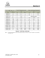
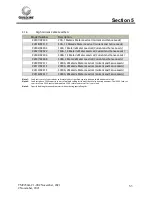
Model 

Test Current Range 

(A) 

Number of Cables in 

Parallel 

Minimum Size 

(AWG) 

9230A-10 

0 to 10 

12 

9230A-15 

0 to 15 

12 

9230A-15R


0 to 15 

12 

9230A-30 

0 to 30 

10 

9230A-50 

0 to 30 

10 

9230A-50 

30 to 50 

9230A-100 

0 to 50 

9230A-100 

50 to 100 

9230A-150 

0 to 75 

9230A-150 

75 to 150 

1/0 

9230A-300 

0 to 150 

1/0 

9230A-300 

150 to 300 

4/0 

9230A-500 

0 to 250 

4/0 

9230A-500 

250 to 500 

MCM350 

9230A-1000 

0 to 500 

MCM350 

9230A-1000 

500 to 1000 

MCM350 

9230A-1500 

0 to 750 

MCM350


9230A-1500 

750 to 1500 

MCM350


9230A-3000 

0 to 2000 

MCM350


9230A-3000 

2000 to 3000 

MCM350


9230A-5000 

0 to 3000 

MCM350


9230A-5000 

3000 to 5000 

10 

MCM350


Table 3-1 :  Cable Size Requirements 


Summary of Contents for 9230A Series

Page 1: ...proprietary to Guildline Instruments Limited They are to be used only as a guide to the operation and maintenance of the equipment with which this manual was issued and may not be duplicated or transmitted by any means either in whole or in part without the written permission of Guildline Instruments Limited TM9230A C1 00 2 November 2021 ...

Page 2: ......
Page 3: ... Standard Shunt Values 3 5 3 5 Cable Connections 3 6 3 5 1 Test Current Cable Requirements 3 6 3 5 2 Test Current Cable Connections 3 6 3 6 Custom Values 3 11 4 0 Calibration and Performance Verification 4 1 4 1 Introduction 4 1 4 2 Calibration Overview 4 1 4 3 Calibration Interval and Performance 4 1 4 4 Calibration Temperature Points 4 2 4 5 Equipment and Standards Required for Calibration 4 2 4...

Page 4: ...A Series from 300 A to 500 A 3 4 Figure 3 3 9230A Series from 1000 A to 5000 A 3 5 Figure 3 4 Single Cable Connection 0 to 500 A 3 7 Figure 3 5 Two Cable Connection 500 A to 1000 A 3 7 Figure 3 6 Four Cable Connection 1000 A to 2000 A 3 8 Figure 3 7 Six Cable Connection 2000 A to 3000 A 3 8 Figure 3 8 Eight Cable Connection 3000 A too 4000 A 3 9 ...

Page 5: ... List Of Tables Table 2 1 9230A Model Series 12 Month Specifications 2 1 Table 2 2 9230A Model Series Specifications Continued 2 2 Table 3 1 Cable Size Requirements 3 10 Table 4 1 Test Points and Currents 4 5 Table 4 2 Calibration Data Worksheet 4 7 ...

Page 6: ... 1 613 283 6082 You can also contact Guildline Instruments Limted via their Email or Websites Email is sales guildline com Website is www guildline com 1 1 Warranty Guildline Instruments warrants its products to be free of defects in manufacture and normal operation for a period of two 2 years from the date of purchase except as otherwise specified This warranty applies only in the country of orig...

Page 7: ...carrier Regular charges will apply to non warranty service External service charges and expenses will be billed at cost plus handling 1 2 To Obtain Warranty or Calibration and Repair Service Call for a Return Material Autorization RMA number RMA s are required for all Warranty Returns and or Calibration and Repair Service Requests Telephone Fax and email addresses to contact Guildline are provided...

Page 8: ...he recommended power will damage the unit although a power level 20 over the limit can be sustained for 1 minute It is recommended to use the model 92310 forced air convection unit whenever power levels above 31 Watts are to be encountered Inspect the Current Shunt Standard for damage such as cracked connectors prior to use If unit has a burned smell or smoke is visible during use discontinue use ...

Page 9: ...000 0 1 m 500 1000 250 25 15 30 9230A 1500 0 05 m 750 1500 250 25 15 30 9230A 3000 10 µ 1500 3000 500 50 20 45 9230A 5000 5 µ 2500 5000 600 70 20 45 Table 2 1 9230A Model Series 12 Month Specifications Note 1 Custom values Customer specified of nominal resistance from 5 µΩ to 1 Ω are available by special order Note 2 Maximum current for natural air convection use without damage to the unit is the ...

Page 10: ... 3 8 5 0 11 2 9230A 500 4 3 10 0 8 114 x 406 x 96 4 5 x 16 x 3 8 5 8 12 9 9230A 1000 20 8 20 2 117 x 539 x 145 4 6 x 21 2 x 5 3 13 0 28 7 9230A 1500 25 10 30 3 117 x 530 x 145 4 6 x 17 2 x 5 3 12 8 28 1 9230A 3000 30 15 30 5 122 x 424 x 216 4 8 x 16 7 x 8 5 29 1 64 9230A 5000 30 20 35 8 122 x 399 x 216 4 8 x 15 7 x 8 5 30 9 68 92310 Option 121 x 242 x 69 4 75 x 9 5 x 2 7 1 0 2 2 Table 2 2 9230A Mo...

Page 11: ...onal uncertainties apply above the 25 Watt power dissipation level 3 2 Design Considerations The Guildline Model 9230A series of four terminal DC current shunt standards provide a number of features for the purpose of minimizing the uncertainties of measurement with respect to environmental factors cable connection variations and long term variations in resistance values Shifts in resistive value ...

Page 12: ...model in the series a very wide dynamic range from virtually zero to full rated current With the use of the Model 92310 Forced Convection Unit full scale power levels at maximum specified test currents vary from 90 W up to 125 W When the shunts are used with natural air convection cooling full scale power levels at the reduced maximum specified test currents vary from 22 5 W up to 31 3 W Performan...

Page 13: ... at the top of the copper posts with two large knobs to hold the current connection cables Separate potential terminal 5 way binding posts are attached to the shunt base along with the shunt element assembly A perforated metal sheet is used to protect the shunt element assembly from physical damage and to allow natural or forced air convection Figure 3 1 illustrates an entire shunt assembly for th...

Page 14: ...he copper terminal plates with two large knobs to hold the connection cables Separate potential terminal binding posts are attached to the current terminal plates as well The shunt element assembly is attached to an insulated base plate A perforated metal sheet is used to protect the shunt element assembly from physical damage and to allow natural or forced air convection Figure 3 2 illustrates an...

Page 15: ...the terminal blocks to provide multiple cable connection points Separate potential terminal binding posts are attached to the top of the current terminal blocks The shunt element assembly is attached to an insulated base plate A perforated metal sheet is used to protect the shunt element assembly from physical damage and to allow natural or forced air convection Figure 3 3 illustrates an entire sh...

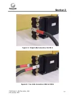
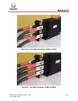
Page 16: ...ly and return test current connections In these cases it is highly recommended to use an even number of cables such that symmetry around the terminal block can be maintained The cable must be of equal length to ensure even current distribution Models for use above 500 A are provided with terminals that incorporate multiple cable connections to ensure that cable connection symmetry can be achieved ...

Page 17: ...Section 3 TM9230A C1 002 November 2021 2 November 2021 3 7 Figure 3 4 Single Cable Connection 0 to 500 A Figure 3 5 Two Cable Connection 500 A to 1000 A ...

Page 18: ...Section 3 TM9230A C1 002 November 2021 2 November 2021 3 8 Figure 3 6 Four Cable Connection 1000 A to 2000 A Figure 3 7 Six Cable Connection 2000 A to 3000 A ...

Page 19: ...Section 3 TM9230A C1 002 November 2021 2 November 2021 3 9 Figure 3 8 Eight Cable Connection 3000 A too 4000 A ...

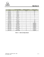
Page 20: ...0 0 to 50 1 4 9230A 100 50 to 100 1 1 9230A 150 0 to 75 1 1 9230A 150 75 to 150 1 1 0 9230A 300 0 to 150 1 1 0 9230A 300 150 to 300 1 4 0 9230A 500 0 to 250 1 4 0 9230A 500 250 to 500 1 MCM350 9230A 1000 0 to 500 1 MCM350 9230A 1000 500 to 1000 2 MCM350 9230A 1500 0 to 750 2 MCM350 9230A 1500 750 to 1500 4 MCM350 9230A 3000 0 to 2000 4 MCM350 9230A 3000 2000 to 3000 6 MCM350 9230A 5000 0 to 3000 6...

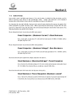
Page 21: ...ale current Power Dissipation Maximum Current 2 x Shunt Resistance For a shunt with a resistance of 1 mΩ and a full scale current of 300 A 90 Watts will be dissipated by the shunt Power dissipation based on resistance and full scale potential Power Dissipation Maximum Voltage 2 Shunt Resistance For a shunt with a resistance of 10 mΩ and a full scale potential of 1 V 100 Watts will be dissipated by...

Page 22: ...suitable additional uncertainties can be applied for local in use conditions Calibration is normally performed with the shunt standard set up on a bench top where the ambient air temperature can be monitored and kept to within 2 ºC For ambient air temperature monitoring purposes with a natural convection setup measure the air temperature approximately 20 mm above the bench top and about 75 mm away...

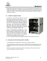
Page 23: ...rovided in the specifications Temperature coefficient measurements are usually performed at a low power dissipation level of 1 Watt to avoid power coefficient effects at higher levels Where a specific temperature coefficient for a shunt standard is required the Guildline Instruments model 5032 Temperature Controlled Air Bath shown to the right is recommended to provide the best calibration environ...

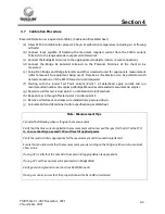
Page 24: ...Resistance Software Guildine 9540 Digital Thermometer 4 6 Routine Calibration This routine calibration procedure describes the calibration currents required for the 9230A Shunt Standards The procedure is intended to be used as a reference for qualified metrology personnel who have a primary level standards laboratory with equipment available to support an instrument of this level of accuracy Quali...

Page 25: ...oceed with the calibration Ensure all equipment used is within the calibration validity interval Before beginning the calibration inspect the UUT for damage and cleanliness If the UUT is not in suitable condition for calibration please clean or repair before proceeding While Table 2 lists recommeded calibration points actual calibration points should include consideration for the intended and or a...

Page 26: ... 50 0 05 10 0 14 1 25 14 1 22 4 50 9230A 100 0 01 22 4 31 6 50 31 6 50 100 9230A 150 0 005 32 45 75 45 71 150 9230A 300 0 001 71 100 150 100 158 300 9230A 500 0 5 m 100 141 250 141 224 500 9230A 1000 0 1 m 224 316 500 316 500 1000 9230A 1500 0 05 m 316 447 750 447 707 1500 9230A 3000 10 µ 707 1000 1500 1000 1581 3000 9230A 5000 5 µ 1000 1414 2500 1414 2236 5000 Table 4 1 Test Points and Currents N...

Page 27: ... of datasheet apply current and run recommended number of samples per Bridge Manual recommended measurement samples g Record results for test value point 1 on Calibration Data Worksheet h Repeat steps b through f for test point 2 and test point 3 i Remove all test leads and make sure standards are powered down j Calculate drift and determine if within specification per Worksheet Note Measurement T...

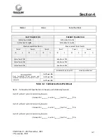
Page 28: ...ation Calculated Drift Note Temperature Power currents and calibration time frame must match for results to be valid Drift Point 1 Drift Point 2 Drift Point 3 Table 4 2 Calibration Data Worksheet Note 1 To Calculate Drift Specifications into ppm use the following formulas For Drift Point 1 µΩ Ω Calculate Using formula Current Cal Value Point 1 Last CalValue Point 1 Last CalValue Point 1 1E6 For Dr...

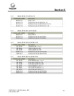
Page 29: ...avoid a high resistance contact that can heat up 5 1 Replaceable Parts The following tables list the replaceable parts Note that once a part has been replaced the unit may be required to be recalibrated To Contact Guildline Instruments the following information is provided USA and Canada Telephone 613 283 3000 USA and Canada Fax 1 613 283 6082 Outside US and Canada Telephone 1 613 283 3000 Outside...

Page 30: ...over for 9230A 500 5 1 4 Models 9230A 1000 and 9230A 1500 Part Number GPN Description 817 01200 Cable Bolt 3 8 16 x 1 839 06666 Cable Flat Washer 3 8 841 01389 Cable Split Washer 3 8 30093 01 15 Perforated Cover for 9230A 1000 3009 02 15 Perforated Cover for 9230A 1500 5 1 5 Models 9230A 3000 and 9230A 5000 Part Number GPN Description 817 01200 End Cable Bolt 3 8 16 x 1 839 06666 End Cable Flat Wa...

Page 31: ... Current and Sense Leads 92309 92311 1000A 2 Meter x Meter Lead set Current and Sense Leads 92312 92313 2000A 2 Meter x Meter Lead set Current and Sense Leads 92314 92315 3000A 2 Meter x Meter Lead set Current and Sense Leads 92316 92317 5000A 2 Meter x Meter Lead set Current and Sense Leads Note 1 Lead sets consist of source leads and return leads of specified capacity and one shielded pair sense...

Reviews: