Section 3
TM9230A-C1-002 November, 2021
2 November, 2021
3-6
3.5
Cable Connections
The size and arrangement of the cables that connect the test current source to the shunt standard are of
most importance to ensure the repeatablity of measurements and the overall quality of the
measurements.
3.5.1
Test Current Cable Requirements
In high current measurements, the cables that carry the test current will heat up due to the resistance
of the cable itself. The temperature of the cable will vary with the size of the cable and the test
current selected. If the cable size is extremely undersized the temperature can increase sufficiently to
melt or burn the cable insulation and can cause damage to the measurement system as well as the
shunt under test. Also the thermal energy will travel through the terminal connection and increase
the temperature of the current terminals of the shunt being measured which will affect its resistance.
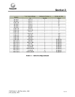
Where test currents above 500 A are required more than one cable will be required on the supply and
return test current connections. In these cases it is highly recommended to use an even number of
cables such that symmetry around the terminal block can be maintained. The cable must be of equal
length to ensure even current distribution. Models for use above 500 A are provided with terminals
that incorporate multiple cable connections to ensure that cable connection symmetry can be
achieved.
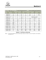
Refer to Table 2 for recommended minimum cable size and number requirements..
3.5.2
Test Current Cable Connections
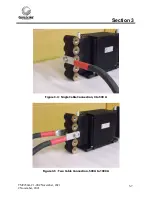
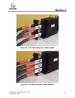
Where multiple connections are required it is important that the symmetry of the connections
horizontally and vertically is maintained around the longitudinal centre line. This requires that only
an even number of cables be used. All the cables that are connected in parallel must be of equal
length and of the same guage so that the test current is distriubuted evenly in each cable.
It is of great importance to ensure that cable connection surfaces are clean and tightened to prevent
high resistance contacts which will cause overheating of the terminal block and effect the realized
resistance value of the shunt.
The following figures illustrate typical connections arrangements for multiple cable connections.
Summary of Contents for 9230A Series
Page 2: ......


