background image

17 

6.1.  Modbus RTU 

Control units communicate on master-slave principle in half-duplex operation. Only master can 

send request and only addressed device responds. During sending of request no other slave station 

should respond. During communication, data transfer proceeds in binary format. Each Byte is sent as 

eight bit data word in format: 1 start bit, data word 8 bit (LSB first), 2 stop bits

1

, without parity. 

Device supports communication speed from 110Bd to 115200Bd. 

 Sent request and response have syntax: ADDRESS OF DEVICE – FUNCTION – Modbus CRC 

6.1.1.  Supported functions 

03 (0x03)

: Reading of 16-bit registers (Read Holding Registers) 

04 (0x04)

: Reading of 16-bit input gates (Read Input Registers) 

06 (0x06):

 Setting of one 16-bit register (Write Register) 

16 (0x10)

: Setting of more 16-bit registers (Write Multiple Registers) 

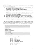
6.1.2.  Jumper 

Jumper (placed nearby keys) is accessible after demounting of four screws in the corners of the 

box and removing the lid. If communication protocol Modbus is selected the function of jumper  is 

as follows: 

Jumper opened – device memory is protected from writing, from device side it is only enabled

to read measured value, writing to memory is disabled (no change of settings is enabled)

Jumper closed – writing to regulator memory is enabled

6.1.3.  Modbus registers of the regulator 

Variable 

Unit 

Address 

[hex]

Address 

[dec]

Format 

Size 

Status 

measured temperature 

[°C/°F]* 

0x0031 

49 

Int*10  BIN16 

measured relative humidity 

[%] 

0x0032 

50 

Int*10  BIN16 

computed value* 

0x0033 

51 

Int*10  BIN16 

Relay1 status [0/1] (Alarm 1) 

[-] 

0x003B 

59 

Int 

BIN16 

Relay2 status [0/1](Alarm 2) 

[-] 

0x003C 

60 

Int 

BIN16 

binary input 1 status [0/1] 

[-] 

0x003D 

61 

Int 

BIN16 

binary input 2 status [0/1] 

[-] 

0x003E 

62 

Int 

BIN16 

binary input 3 status [0/1] 

[-] 

0x003F 

63 

Int 

BIN16 

status of all binary inputs 

(bit0, 1, 2) 

[-] 

0x0008 

Int 

BIN16 

status word (described below) 

[-] 

0x0007 

Int 

BIN16 

device serial number Hi 

[-] 

0x1035 

4149 

BCD 

BIN16 

device serial number Lo 

[-] 

0x1036 

4150 

BCD 

BIN16 

firmware version Hi 

[-] 

0x3001 

12289 

BCD 

BIN16 

firmware version Lo 

[-] 

0x3002 

12290 

BCD 

BIN16 

device address 

[-] 

0x2001 

8193 

Int 

BIN16  R/W** 

communication speed code 

[-] 

0x2002 

8194 

Int 

BIN16  R/W** 

1


Device sends two stop bits, for receive one stop bit is enough. 

Summary of Contents for AR006683

Page 1: ...Temperature humidity and pressure regulator with RS232 serial output AR006684 AR006683 Instruction Manual ...

Page 2: ... 1 Supported functions 17 6 1 2 Jumper 17 6 1 3 Modbus registers of the regulator 17 6 1 4 Far controlling of output relays status 18 6 1 5 Output relay alarm condition configuration with using of Modbus communication protocol 2 19 6 2 PROTOCOL COMPATIBLE WITH ADVANTECH ADAM STANDARD 20 6 2 1 Jumper 21 7 ERROR STATES OF THE DEVICE 22 8 READINGS ON LCD DISPLAY 23 9 PREVENTIVE MAINTENANCE AND CALIBR...

Page 3: ...ables if the device is under electric voltage Do not use the instrument without the cover Do not use the instrument if it does not work correctly If the instrument seems not to work correctly have it checked by a qualified service person Do not use the instrument in an explosive environment Read instruction manual before the first device connection please Copyright It is prohibited to copy and edi...

Page 4: ... Modbus RTU communication protocol If you would like to use different communication protocol then Modbus RTU it is necessary preset them see latter Temperature relative humidity and pressure sensors are non removable instrument parts except H4431 device that is designed for two wires connection of external Pt1000 temperature sensor Measured and computed values are displayed on dual line LCD It is ...

Page 5: ...es with shielding The probe cable length and size of conductor affects measurement accuracy If connected probe is equipped with metal stem we recommend using probes with metal stem not connected to cable shielding Or else it is necessary to arrange metal stem is not connected to any other circuitry The cables for binary inputs and external sensor for regulator AR006683 must be placed as far as pos...

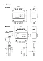
Page 6: ...6 3 Dimensions AR006683 AR006684 Probe for compressed air measurement ...

Page 7: ...facturer communication protocol Modbus RTU regulator address 1 communication speed 9600Bd no parity 2 stop bits Value assigned to Relay1 and Relay2 none Password for setting through keys PASS 0000 on temperature temperature pressure by device type relative humidity dew point temperature C hPa 0 hPa absolute pressure dew point temperature stay unchanged at previous condition LED diode lights if inp...

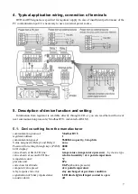
Page 8: ...ee galvanically not isolated binary inputs It is possible to connect open contact or external voltage Auxiliary power supply U terminal can be used to supplying of external sensors and detectors Visualization of binary inputs is done by three LED diodes placed on the left side from LCD Green one represents input Binary 1 yellow input binary 2 and red input binary 3 If binary input is not connected...

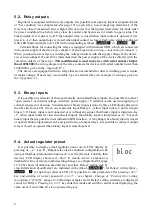
Page 9: ...tion 1 after device s power on the relay is close If far condition is assigned to output relay then there is possible to change the output relay status by Modbus communication protocol only See chapter 6 1 4 at page 18 5 4 2 When close output relay High limit HI the relay closes when measured value exceeds preset high limit for longer time than preset delay time Relay goes open when measured value...

Page 10: ...rews in the corners of the box and removing the lid This jumper is suitable e g until device adjustment is in process and regulator is placed into calibration box and keys are not accessible Don t forget to remove open jumper after procedure finish restore write protection TSensor software supports to make the adjustment of the regulator too This procedure is described at file Calibration manual p...

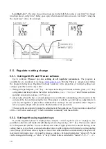
Page 11: ...e to change parameters available through Actual regulator preset only see chapter 5 4 at page 8 Rest of regulator parameters are available through Extended setting mode In this mode regulator does NOT communicate does NOT do any measurements and does NOT service output relays To leave this mode press ESC key and open jumper nearby keys To enter into Extended setting mode do following steps 1 disco...

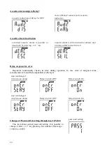
Page 12: ...te it Relay response for error Regulator continuously checks its state during operation In case error of assigned value measurement is found then output Relay1 Relay2 stays unchanged in previous status Relay1 switch OFF Relay1 switch On stays unchanged in previous status Relay2 switch OFF Relay2 switch On Change of Password for setting through keys PASS This item shows actual password setting It i...

Page 13: ...etting Visualization of binary inputs Visualization of inputs is done by three LED diodes This option defines at which binary input status should LED diode indication lights LED diode lights if binary input is OPEN or CLOSED LED lights if binary input is OPEN LED lights if binary input is CLOSED Binary input 1 similarly 2 3 Temperature unit choice It is possible to measure temperature at C or F Th...

Page 14: ...ble to set corresponding pressure offset for this altitude It is possible to change it after SET key pressing Pressure correction value is then automatically added to measured pressure value See chapter Error States of the device at page 22 Error 2 correction for altitude pressure correction value is from 25 0 to 650 0 hPa 0 363 to 9 427 PSI 0 74 to 9 19 inHg 25 0 to 650 0 mBar 5 8 to 150 8 oz in2...

Page 15: ... line see Computed value selection below It is possible to change it after SET key pressing show value on LCD don t show value on LCD Show barometric pressure at LCD display This item provides to choice if actual barometric pressure may be displayed at LCD display or not It is possible to change it after SET key pressing show value on LCD don t show value on LCD Computed value selection It shows t...

Page 16: ...ure pressure by device type value shown at second LCD line relative humidity dew point temperature temperature unit C pressure unit hPa correction for altitude 0 hPa absolute pressure computed value preset dew point temperature restore to factory default 6 Description of communication protocols Detailed description of each communication protocols including examples of communication is available in...

Page 17: ...ion of jumper is as follows Jumper opened device memory is protected from writing from device side it is only enabled to read measured value writing to memory is disabled no change of settings is enabled Jumper closed writing to regulator memory is enabled 6 1 3 Modbus registers of the regulator Variable Unit Address hex X Address dec X Format Size Status measured temperature C F 0x0031 49 Int 10 ...

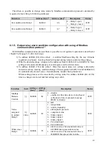
Page 18: ...lay1 open closed Bit4 0 1 Relay2 open closed Bit5 0 1 internal acoustic alarm status Bit6 0 1 binary input 1 status Bit7 0 1 binary input 1 status Bit8 0 1 binary input 1 status Bit9 to 15 unused Note In case there is a need for reading of measured values from the device with higher resolution than one decimal measured values in device are stored also in Float format which is not directly compatib...

Page 19: ...be done simultaneously or each register can be written alone 3 To address 0x004F 79 write value 1 Once this step is done new setting is physically stored into device memory confirm change Then registers 0x004F 79 and 0x0044 68 are automatically cleared zero It automatically unlocks the keyboard too Whole setting process can be cancelled by writing value 0 to address 0x0044 68 At this time no chang...

Page 20: ...lay2 sec 0x004D 77 Time in seconds Time in seconds that the condition must be valid to evaluate alarm R W Hysteresis of Relay2 by value 0x004E 78 Value which must be set back below above a given threshold in order to open the relay R W Confirm changes 0x004F 79 Read always as 0 write 1 physically stores new setup into device s memory at the end the register is automatically reset to zero R W All r...

Page 21: ...auses restoring of manufacturer setting of communication protocol i e sets Modbus RTU communication protocol device address sets to 01h and communication speed to 9600Bd after button press there is dEF message blinking at LCD display Six seconds later message dEF stays shown it means manufacturer setting of communication protocol is done For communication with device which measure more than one va...

Page 22: ...e appears in case of Measured temperature is lower than approximately 210 C i e low resistance of temperature sensor probably short circuit Relative humidity is lower than 0 i e damaged sensor for measurement of relative humidity or calculation of humidity is not possible due to error during temperature measurement Measured pressure value with added correction for altitude is outside of range from...

Page 23: ...number without corresponding unit 9 Preventive maintenance and calibration Pay heed to recommended calibration interval Do not subject the device to mechanical stress 10 Technical specification 10 1 Technical parameters 10 1 1 Common parameters Power voltage 9 to 30 V DC Power consumption approx 1 W consumption of sensors and detectors connected to U terminals Measuring interval temperature relati...

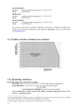
Page 24: ...temperature and humidity range is limited in accordance with the graph below Response time with stainless steel mesh sensor cover F5200B and bronze sensor cover F0000 selectable option air flow approximately 1 m s temperature AR006684 t90 6 min temperature step 20 C 36 F relative humidity t90 30 s humidity step 65 RH constant temperature 10 1 3 AR006683 temperature regulator external probe designe...

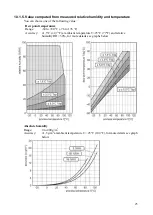
Page 25: ...owing value Dew point temperature Range 60 to 80 C 76 to 176 F Accuracy 1 5 C 2 7 F at ambient temperature T 25 C 77 F and relative humidity RH 30 for more details see graphs below Absolute humidity Range 0 to 400 g m3 Accuracy 1 5 g m3 at ambient temperature T 25 C 104 F for more details see graph below ...

Page 26: ...idity and temperature restriction 10 2 Operating conditions Operating temperature and relative humidity electronics 30 to 80 C 22 to 176 F 0 to 100 RH without condensation probe AR006684 30 to 105 C 22 to 221 F probe cable included 0 to 100 RH external probe for AR006683 by probe type not included It is recommended to switch off the LCD display at ambient temperatures above 70 C 158 F around elect...

Page 27: ...r other liquids It is not allowed to remove the sensor cover to avoid any mechanical damage of the sensors Storage conditions 30 to 80 C 22 to 176 F 0 to 100 RH without condensation Dimensions see dimensional drawings Weight approximately AR006683 430 g AR006684 1m probe 500 g AR006684 2m probe 540 g AR006684 4m probe 620 g Material of the case ABS 10 3 End of operation Device itself after its lif...

Page 28: ...2 closing valve 3 probe 4 flow chamber SH PP 5 closing valve 6 outlet tube sampling 1 end of the tube placed in the centre of pressure pipelines distribution of moisture in the pipe cross section is not homogeneous To achieve fast response times to shorten the length of the sample tubes to a minimum few meters closing valve 2 allows access to the sample system without interrupting the main line cl...

Page 29: ...ains basic information about connection of the detectors optional accessories to binary inputs of regulator The detectors install in accordance with the attached instructions for use SP008 power detector AC voltage presence sensor with optical indicator green LED input voltage 230Vac 50Hz power plug type C response time approx 1 sec LD 12 flood detector This detector is a water flood indicator for...

Page 30: ...y is used connect the terminals ALARM to the terminals GND and IN1 If the detector is powered from the regulator it is necessary to use power supply of 12Vdc for power supplying the regulator Notice The connecting cables should be located as far as possible from the potential interference sources The cable shield connect to Shield terminal of regulator only 14 Appendix D Wiring diagram of relay co...

Reviews: