l
22
Dynamic Blanking Zones
The Dynamic Blanking Zone is used to mask a segment of the scan rotation. When the
scanner passes through the dynamic blanking zone, the laser is switched off to prevent
any unwanted reflections from being mistaken as targets.
N.B. Even if the sensor has a clear 360° view, there must be a dynamic blanking zone of
at least 23°. The user interface will not allow smaller blanking zones.
Generally, once the dynamic blanking zone has been set, it will not need to be changed.
However, there may be occasions when it is necessary to adjust the dynamic blanking
zone, for example if the target is on the opposite side of the vessel to normal.
Note:
Up to four additional static blanking zones can be configured from within the
CyScan Service Interface. These are typically used to mask vessel structure. (see 94-0559
CyScan AS Installers Guide).
Setting the Dynamic Blanking Zone
The start and end of the zone can be set to any positions around the circle to the nearest
degree, subject to the minimum and maximum sizes of the zone (see red box below).
To define the Dynamic Blanking Zone
The Dashboard needs to be in command mode to make changes to the dynamic blanking
zone.
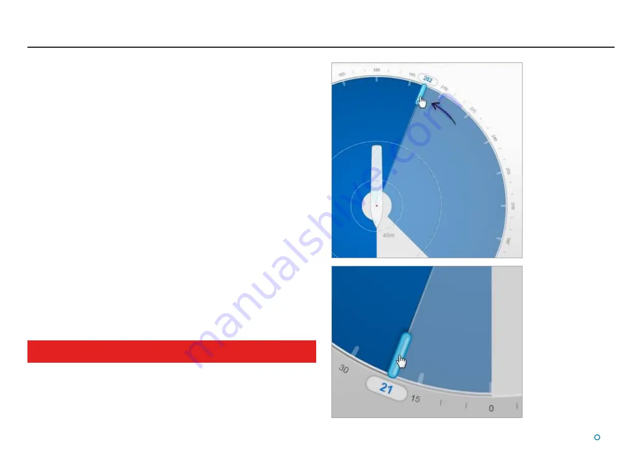
1. Click one of the dynamic blanking zone handles and, holding down the left mouse
button, drag to the desired position. Alternatively - on a touchscreen - touch and drag.
As the handle is moved, its current position (in degrees clockwise from the vessel bow)
is displayed in blue numerals outside the perimeter of the circle.
2. If required, drag the second zone handle in the same way.
3. The Apply-Cancel buttons will have popped up after step 1. Click on the
Apply
button
to set the dynamic blanking zone, or on
Cancel
to restore the dynamic blanking zone
to its previous state.
The dynamic blanking zone must cover at least 23° but no more than 337°. The user
interface will not allow larger blanking zones.
Summary of Contents for CyScan AS
Page 62: ......


