GST SMR-IP10-D Installation & Operation Manual Download Page 1

Technicians Installation & Operation Guide
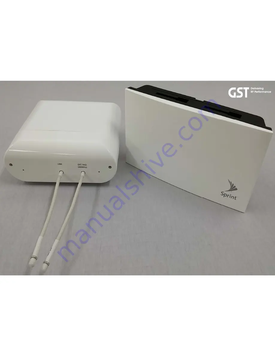
Model: SMR-IP10-D

SMR-IP10-S 

Version 1.0

GS Teletech Inc.

Confidential and proprietary to GS Teletech Inc.
Copying, reproduction or distribution this information is strictly prohibited
without prior written authorization from GST.

Summary of Contents for SMR-IP10-D

Page 1: ...n Guide Model SMR IP10 D SMR IP10 S Version 1 0 GS Teletech Inc Confidential and proprietary to GS Teletech Inc Copying reproduction or distribution this information is strictly prohibited without pri...

Page 2: ...IP10 D S Smart Mobile Repeater for 800MHz and 1900MHz Bands Application Small Business Enterprise and Public venues Coverage Up to 5k sq ft per unit SMR IP10 2 Technician s Installation Operation Gui...

Page 3: ...ser Interface in this publication may vary depending on it s S W version Copyright 2015 GS Teletech Inc All Rights Reserved Printed in the Republic of Korea Version History Certification UL FCC This e...

Page 4: ...o the repeater RF EXPOSURE ANTENNA PLACEMENT Actual separation distance is determined upon gain of antenna used Please maintain a minimum safe distance of at least 8 inch while operating near the dono...

Page 5: ...nnected Consult the dealer or an experienced radio TV technician for help FCC Part 15 21 statement Any changes or modifications not expressly approved by the party responsible for compliance could voi...

Page 6: ...Link Cable Jumper AC Cord DAU Bracket Set AC DC Adaptor Contents of Box 1 2 6 Technician s Installation Operation Guide SAU Bracket Set DAU SAU...

Page 7: ...5 AC Power Cord 1 6 Quick Installation Guide 1 No Item Q ty Picture 7 Operation and Troubleshooting Guide 1 8 DAU Bracket Set 1 Tapping screw PH 5X25 Anchor bolt 4 9 SAU Bracket Set 1 Tapping screw P...

Page 8: ...Donor Antenna Unit DAU Service Antenna Unit SAU Repeater Design 8 Technician s Installation Operation Guide SMR IP10 D SMR IP10 S...

Page 9: ...DAU SMR IP10 D Dimensions 9 Technician s Installation Operation Guide 209 W X 190 H X 74 D mm 8 2 W X 7 4 H X 2 9 D in Repeater Design Donor Antenna Unit DAU...

Page 10: ...SAU SMR IP10 S Dimensions 10 Technician s Installation Operation Guide 252 W X 148 H X 54 D mm 9 9 W X 5 8 H X 2 1 D in Repeater Design Service Antenna Unit SAU...

Page 11: ...0MHz Frequency Bands 11 Technician s Installation Operation Guide Service Band Blocks 800MHz Band 1900MHz Band 817 824 869 862 A D B E F C G A D B E F C G 1850 1910 1915 1930 1990 1995 LTE 819 864 CDM...

Page 12: ...troduction DAU SAU RG174 Cable Non Flammable 12 Technician s Installation Operation Guide The SMR IP10 is a paired repeater solution consisting of a Donor Antenna Unit DAU and a Service Antenna Unit S...

Page 13: ...gnal level is weak less than 95dBm installer may connect the DAU to 800MHz external donor antenna for receiving and transmitting signals from 800MHz Base Station Check measurement criteria via WebGUI...

Page 14: ...enough distance between the Donor Antenna Unit and the Service Antenna Unit to prevent oscillation Install the SAU on the wall or ceiling Install the SAU in a location where people cannot easily reac...

Page 15: ...sic Structure Recommended Link Cable Loss consideration is necessary if extended 1 External Antenna Built in antenna 2 External Antenna Link Cable Loss consideration is necessary if extended Link Cabl...

Page 16: ...nk Cable loss consideration is necessary if extended Cable Loss should be considered Cable Loss should be considered When using 4 dividers the following architecture will be applicable and the divider...

Page 17: ...than the Uplink coverage For example when the input signal level of Donor Antenna Unit DAU is 90dBm and coverage is 15m the total loss of service side is necessary to make less than 15dB Donor input l...

Page 18: ...on Measurement Retail Sales Area EVDO 800 MHz 1900 MHz DL Throughput Mb sec N A Over 80 of outdoor measurement UL Throughput Mb sec N A Over 80 of outdoor measurement LTE 800 MHz 1900 MHz DL Throughpu...

Page 19: ...Cable Length 50m 164 ft 19 Technician s Installation Operation Guide Link cable Installation Guideline...

Page 20: ...ely 3 8 inch Coaxial Cable 180m 590ft 270m 885ft Approximately 1 4 Coaxial Cable 50 ohm 3 8 Coaxial Cable 50 ohm 1 8 Coaxial Cable ohm Strongly recommended DC Drop No Problem AC DC Adaptor DC Source 1...

Page 21: ...dBm 95dBm or above 95dBm or above Ec Io dB 12dB or above 12dB or above EVDO 800 MHz 1900 MHz PN N A Serving Physical Cell Identity RSSI dBm N A 95dBm or above Ec Io dB N A 12dB or above LTE 800 MHz 19...

Page 22: ...less EVDO 800 MHz 1900 MHz PN N A Serving Physical Cell Identity RSSI dBm N A 95dBm or less LTE 800 MHz 1900 MHz PCI Serving Physical Cell Identity Serving Physical Cell Identity RSRP dBm 105dBm or l...

Page 23: ...TX power N A 0dBm or less DL Throughput Mb sec N A Over 80 of outdoor measurement UL Throughput Mb sec N A Over 80 of outdoor measurement LTE 800 MHz 1900 MHz PCI Serving Physical Cell Identity Servin...

Page 24: ...MHz External antenna connection If required SAU Link Cable port CAUTION Do not connect or disconnect cable from ANT port when power is ON Cable Connections Technician s Installation Operation Guide 24...

Page 25: ...required SMA F DAU Bottom Side 1 2 Repeater Port Design 25 Technician s Installation Operation Guide Donor Antenna Unit In special cases the DAU s EXT ANT can be connected with a high gain antenna for...

Page 26: ...Port WebGUI RJ45 Link Cable Connection Power On Off AC DC Adaptor Left Side Right Side LED Indicator Band Information Signal Strength Bottom Side Repeater External Port Design 26 Technician s Install...

Page 27: ...nal Checking DAU Mounting Link Cable Connection Cabling to SAU SAU Mounting AC outlet construction Link Cable Connection AC DC Adaptor Connection SAU Switch On Check LED Status Finish YES Locate the D...

Page 28: ...BTS BTS BTS Positioning of DAU 28 Technician s Installation Operation Guide Search for the proper BTS location Please refer to Measurement Criteria...

Page 29: ...ing holes on the wall 3 Drill holes in the wall at the locations marked in step 1 4 Set the anchors in the wall position the bracket and tighten tapping screws until secured 5 Put the DAU into mountin...

Page 30: ...The DAU should be installed pointing toward a Base Station to receive clear and stable CDMA LTE signals Mounting SMR IP10 30 Technician s Installation Operation Guide Installed DAU Example...

Page 31: ...n for both 800MHz and 1900Mhz Collocated Site DAU installation Only recommended Individual Site DAU recommended but if required add 800MHz antenna If required External Antenna Installation for 800MHz...

Page 32: ...individual BTS site for both 800MHz and 1900MHz network DAU 800MHz External Antenna Direction of 1900MHz BTS Direction of 800MHz BTS If required 32 Technician s Installation Operation Guide Installed...

Page 33: ...t attached on DAU module Upgrading Existing Repeater With SMR IP10 If necessary 33 Technician s Installation Operation Guide Jumper cable connection for adapting both 800MHz and 1900MHz 1 Open DAU 2 L...

Page 34: ...Donor Antenna Connection and Replacement of existing Repeater GS Teletech Inc Upgrading Existing Repeater With SMR IP10 Replacement of existing repeater Existing Donor Antenna for both 800MHz and 190...

Page 35: ...in the wall at the locations marked in step 1 3 Set the anchors in the wall position the bracket and tighten tapping screws until secured 4 Put the SAU into the mounting bracket 5 Tighten the mounting...

Page 36: ...uld be well positioned to provide the best CDMA LTE service and coverage Service Coverage and Quality 36 Technician s Installation Operation Guide Service Quality Measurement Please refer to Measureme...

Page 37: ...t can be used to add external service antenna s Once the external service antenna port is used the internal SAU antenna will be disabled External Port of SAU 37 Technician s Installation Operation Gui...

Page 38: ...lity 38 Technician s Installation Operation Guide Service Quality Measurement GS Teletech Inc The SAU should be well positioned to provide excellent CDMA LTE service and coverage Please refer to Measu...

Page 39: ...on Description 1 Checking GREEN LED Blinking in sequence PWR 1900 800 Auto Setup 2 Normal PWR GREEN LED ON Alarm_1900 GREEN LED ON Alarm_800 GREEN LED ON Standard operation Power 800MHz Alarm 1900MHz...

Page 40: ...l between DAU and SAU 5 Alarm Alarm_1900 RED LED Blinking Power RED LED Blinking Lack of Isolation between DAU and SAU 1900 6 Alarm Alarm_800 RED LED Blinking Power RED LED Blinking Lack of Isolation...

Page 41: ...stallation Operation Guide Frequency Band Service Instruction Bandwidth 1900MHz A D and B Select one band 5MHz or 10MHz or 15MHz E F and C Select one band 5MHz or 10MHz G 5MHz 800MHz CDMA 2MHz CDMA LT...

Page 42: ...or 10MHz or 15MHz E F and C Select one band 5MHz or 10MHz G 5MHz 800MHz CDMA 2MHz CDMA LTE 7MHz Block Info 1900 Push Block Info button for 10 seconds to return to Factory Default Settings None of the...

Page 43: ...equency Instruction Description Block Info 1900 Band Information 1900MHz Service Block Information Signal Strength 800 1st Click 800MHz Input Signal Level RSSI 2nd Click 800MHz Output Power Level 1900...

Page 44: ...LED Level Bar A D B E F C G Items LED Values Status Input Signal Level A blinking 85dBm below Bad AD 84dBm 75dBm Satisfactory ADBE 74dBm 70dBm Good ADBEFC 69dBm above Excellent Output Power G blinkin...

Page 45: ...e repeater can be accessed locally with a cross over UTP cable or remotely with an optional external modem The images for the User Interface in this publication may vary depending repeater s S W versi...

Page 46: ...46 Technician s Installation Operation Guide IP Address 192 168 1 1 Log In...

Page 47: ...Easy Setup 47 Technician s Installation Operation Guide...

Page 48: ...Professional Setup 48 Technician s Installation Operation Guide...

Page 49: ...You can check the status of the RF operation on the status page RF Status 1900MHz band 49 Technician s Installation Operation Guide...

Page 50: ...You can check the status of the RF operation on the status page 50 Technician s Installation Operation Guide RF Status 1900MHz band...

Page 51: ...RF Configuration RF changes can be made on the RF configuration page 51 Technician s Installation Operation Guide...

Page 52: ...RF Configuration 52 Technician s Installation Operation Guide RF changes can be made on the RF configuration page...

Page 53: ...Alarms and SNMP mapping can be configured on the Alarm Configuration page Alarm Configuration 53 Technician s Installation Operation Guide...

Page 54: ...The alarm logs page allows you to check the system alarms Alarm Logs 54 Technician s Installation Operation Guide...

Page 55: ...You can configure alarming remote access on the Communication Configuration page Communication Configuration 55 Technician s Installation Operation Guide...

Page 56: ...You can configure alarming remote access on the Communication Configuration page Communication Configuration 56 Technician s Installation Operation Guide...

Page 57: ...You can configure alarming remote access on the Communication Configuration page Communication Configuration 57 Technician s Installation Operation Guide...

Page 58: ...75dB 2dB AGC dynamic Range 40dB Gain Flatness DL UL 2dB Any sub band Composite Output Power ERP Effective Radiated Power DL 10dBm Total 1x EVDO LTE UL 10dBm Total Composite Output Power EIRP Effectiv...

Page 59: ...x EVDO 1x EVDO 0 912 In Out VSWR DL UL 2 1 Roll off DL UL 50dBc F edge 1MHz Out of band Spurious Emissions DL UL 45dBc Fc 885kHz Meet FCC Title 47 CFR Part 15 22 24 50dBc Fc 1 98MHz 13dBm Fc 2 25MHz R...

Page 60: ...iated Power DL 10dBm Total CDMA LTE UL 10dBm Total Composite Output Power EIRP Effective Isotropic Radiated Power DL 10dBm Total Coverage Ant Gain 0dBi UL 15dBm Total Donor Ant Gain 5dBi Shutdown Leve...

Page 61: ...UL 65dBc F edge 1MHz Out of band Spurious Emissions DL UL 45dBc Fc 885kHz Meet FCC Title 47 CFR Part 15 22 24 50dBc Fc 1 98MHz 13dBm Fc 2 25MHz RBW 1MHz Noise Figure UL 7dB Max gain Technical Specifi...

Page 62: ...er ON OFF SIZE H x W x D DAU 6 69 x 7 67 x 2 67 Inch 170x195x68 mm SAU 9 64 x 5 90 x 2 20 Inch 245x150x56 mm Weight DAU 3 52 lbs 1 6 Kgs SAU 3 52 lbs 1 6 Kgs User Interface Local GUI Web UI Operating...

Page 63: ...Remark 1 Impedance 50 Nominal 2 Frequency 10 MHz 350 MHz 3 V S W R 1 2 1 4 Insertion Loss 3 5dB 25dB 5 Contact Resistance Center Contact 3 0m Max Outer Contact 2 5m Max 6 Insulation Resistance 5 000...

Page 64: ...king stage when the isolation between DAU built in antenna and SAU built in antenna is not enough 4 Alarm Low Input Voltage DAU needs to have more than 12VDC of Input DC power Check connection of Link...

Page 65: ...installation guide are subject to change without notice or obligation GST Technical Support Toll Free 1 866 9 GST USA Phone 913 469 6699 GS Teletech Inc 320 NW Victoria Drive Lee s Summit MO 64086 US...

Reviews: