30308778 Issue 1.06
Features
Two-wire
and
four-wire
modes
can
be
programmed through hand held programmer.
Electronic address can be modified in field.
Built-in MCU processes messages intelligently.
Monitoring power supply.
Fault and action indicators available.
Four wire output cable checking.
Plug-in structure.
Standard: EN 54-18:2005.
Description
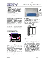
I-9301 Addressable Single Output Module works in
two-wire mode and four-wire mode.
In four-wire mode, on receiving start command from
the fire alarm control panel (FACP), it will close the
output relay to output 24VDC and illuminate the
Active indicator. If there is short, open circuit, or
power down, the module can check failure and report
it to the FACP.
In two-wire mode, on receiving start command from
the fire alarm control panel (FACP), it will close the
output relay to output normally-open normally close
contact signal and illuminate the Active indicator.
Connection and Cabling
Fig. 1 shows terminals on the module.
1
2
7
8
16
15
10
9
65
S+
5
R
10
S-
COM NC
D1
D2
Z2
Z1
Bottom Cover(Remove Top Cover And Terminal Plate)
NO
I-9301
Fig. 1
Z1, Z2: Connecting with loop of FACP, polarity-insensitive.
D1, D2: 24VDC power cable, polarity-insensitive
(only for four-wire mode).
S+, S-: Output for four-wire mode, polarity-sensitive.
Connecting with D1 (9), D2 (7) of C-9403. S+
connects with D1(9), and S- with D2(7).
NC, COM, NO: Normally open and normally close
terminals for two-wire mode.
Recommended Wiring
1.5mm
2
or above fire cable for 24VDC, 1.0mm
2
or
above fire cable for others, subject to local codes.
Installation
The module is simply plugged onto the base after
corresponding terminals are connected.
If the cable conduit is on the surface of the wall, the
B-9310 Back Box is available. Note the upward
arrow for mounting direction (Fig.1).
Conduit
B-9310
Back Box
Conduit
Module
Module
Back Box
Fig. 2
Application
The module connects with fire control devices such
as lifts and fire doors which are activated by FACP.
The address and working mode of the module can
be programmable by a GST programmer in field.
Please refer to
P-9910B Hand Held Programmer
Installation and Operation Manual
for details. Factory
default mode is two-wire (number
“2”). Four-wire
mode (number
“1”) can be programmed in field.
The module connects with C-9403 conventional
sounder strobe. Its system connection is shown in
Fig. 3. Working mode should be set to four-wire (1),
volt output for S+, S- should connect with 4.7
kΩ
resistor in parallel (refer to Fig. 3).
I-9301
Addressable Single Output Module
548m/02
0832-CPD-0838


