- 7 -
HDTA 614 T ASI
b
loCk
diagr a m
Tuner "
A
"
SAT IN "
A
"
ASI IN
RF OUT
Tuner "
D
"
TPS
TPS
TPS
TPS
CA-Modul
CA module
CA-Modul
CA module
Tuner "
B
"
Tuner "
C
"
SAT IN "
B
"
Modulator
"
A
"
Modulator
"
B
"
Modulator
"
C
"
Modulator
"
D
"
Combiner
LNB
In A
Bx 4A
10600 MHz
Bx 4
0 x ASI
ASI
OFF
g
ener al
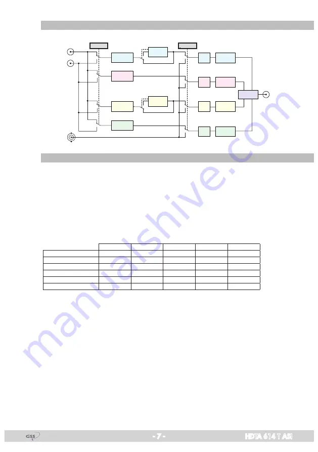
The cassette is equipped with four channel strips ("
A
" … "
D
"). The channel
strips consist of the digital tuners, the digital signal preparation units and the
output converter. The channel strips are indicated in the head-end station dis-
play with "
Bx …A
" … "
Bx …D
". Using adequate CA modules scrambled
channels can be descrambled via tuner "
A
" and "
C
".
As signal source of the channel strips, tuners or the ASI input can be selected
according to the table below:
Line A
Line B
Line C
Line D
CA
0xASI
OFF
Tuner A
Tuner B
Tuner C
Tuner D
2
1xASI
D
Tuner A
Tuner B
Tuner C
ASI
2
2xASI
B/D
Tuner A
ASI
Tuner C
ASI
2
2xASI
C/D
Tuner A
Tuner B
ASI
ASI
1
3xASI
B/C/D
Tuner A
ASI
ASI
ASI
1
4xASI
A/B/C/D
ASI
ASI
ASI
ASI
0
The control of the cassette takes place via the control unit of the head-end station.
Four LEDs provide an indication of the SAT IF input signal quality based on
their colour and indicate if the respective channel strip is switched on (LED il-
luminates) or off.
The integrated TPS module (Transport Stream Processing) processes the data
of the transport streams.
Channel as well as frequency setting is possible for modulators "
A
" and "
C
".
The modulators "
B
" and "
D
" work at the adjacent channels of modulators"
A
"
and "
C
". Herein only frequency setting (frequency spacing of channel strips
"A <–> B" and "C <–> D") is possible to reduce the bandwidth at signals of
low data rates.


