4. Installation
PNEG-1901CE
CE Compliant Downwind Centrifugal Heater Installation and Operation
23
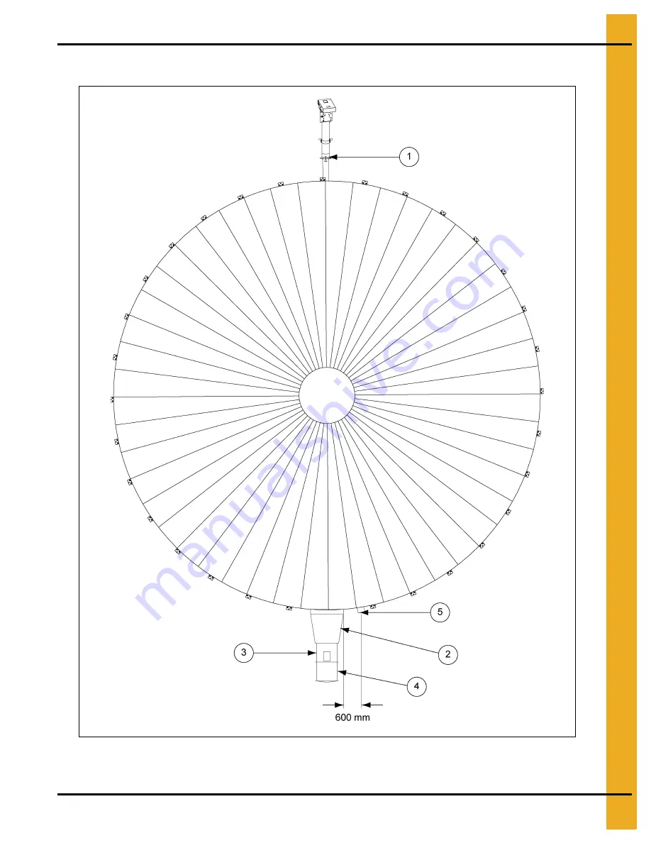
Fit Heater to Bin
Figure 4J Single Heater Installation
NOTE:
Orientation of fan relative to unload must be as shown. See table on
Page 24
.
Page 1: ...PNEG 1901CE CE Compliant Downwind Centrifugal Heater Installation and Operation Model ____________ Serial ____________ Owner s Manual Original Instructions PNEG 1901CE Date 08 07 13...
Page 2: ...meet the requirements of the following standards EN746 2 1996 The equipment above must not be put into service until the machinery into which it is to be incorporated has been declared in conformity w...
Page 3: ...HF 7200 120 C 25 Fit Plenum Thermostat High Limit 27 Electrical Installation 28 CE Heater Control Schematic 29 CE Heater Control Connections 30 Modulating Valve Installation Optional 31 Connect Fuel S...
Page 4: ...ntion to these sections Failure to read this manual and its safety instructions is a misuse of the equipment and may lead to serious injury or death DANGER WARNING CAUTION NOTICE This is the safety al...
Page 5: ...uld be carefully followed in all cases Authorities having jurisdiction should be consulted before installations are made Follow Safety Instructions Carefully read all safety messages in this manual an...
Page 6: ...debris Wear gloves to protect your hands from sharp edges on plastic or steel parts Wear steel toed boots to help protect your feet from falling debris Tuck in any loose or dangling shoestrings A res...
Page 7: ...t facility on the bin store dryer It shall NOT be used 1 With any safety features by passed 2 For domestic or commercial heating 3 In any potentially explosive area 4 By an untrained person or any one...
Page 8: ...djacent to each heater b Disconnects all power to the heater 4 Emergency stops a Stops all equipment immediately when pressed b Must remain engaged until manually disengaged c Equipment shall not imme...
Page 9: ...shall not immediately re start following re establishment of power 9 All electrical design installation and testing must be carried out by a qualified electrical engineer in accordance with EU Direct...
Page 10: ...e if you stand on it It is recommended NEVER to walk on the surface of the stored material If grain has stopped flowing become bridged capped or crusted the only safe way to remedy this is from the ou...
Page 11: ...clean out doors and blow out excess dust and chaff 8 Check inside other dryer accesses and clean as required 9 Check all personnel are out of the dryer close and lock all accesses before re starting...
Page 12: ...on and or makeup air devices should be provided for all powered air handling systems GSI does not recommend the use of downward flow systems suction Severe roof damage can result from any blockage of...
Page 13: ...a macchine automatiche automatiska maskiner Otomatik Makina M quinas autom ticas Aparate Automaattinen Machinery AIRFLOW AIRFLOW CIRCULATION D AIR CIRCULATION D AIR DC 1971 DC 2162 GSI Group 217 226 4...
Page 14: ...e contact pour reinitialiser la limite l v e DC 1165 DANGER DC 2213 GSI Group 217 226 4421 DC 1702 On lid DC 1973 Inside control DC 2213 On lid DC 2163 Inside control DC 1973 Hi Limit Reset Button Lim...
Page 15: ...2 Safety Decals PNEG 1901CE CE Compliant Downwind Centrifugal Heater Installation and Operation 15 Figure 2D DC 2215 also at eaves hatch DC 2215 GSI Group 217 226 4421 DC 2215 GSI Group 217 226 4421...
Page 16: ...56789 VHE 18 VNC 512 kW 48 kPa 20 5 kPa 28 5 kPa 48 kPa 38 3 m3 h 12 2 m3 s 15 5 m3 s 220 240VAC 1 50 hz 2 0 A 14 5 m3 h 33 9 m3 h Min Max 82 4 m3 h 6 3 mm 379 kW 6 3 mm 2 5 mm 9 5 mm 1185 kW 884 kW N...
Page 17: ...ownwind Centrifugal Heater Installation and Operation 17 3 Specifications Figure 3A Heater Dimensions mm IH IW L CHE 10 768 495 838 CHE 15 768 495 838 CHE 20 768 495 838 CHE 25 845 552 838 CHE 30 845...
Page 18: ...253 0 317 0 379 0 427 0 512 0 Low Temp Fuel Flow at Maximum Pressure m3 h 7 7 9 7 12 2 14 5 16 4 19 6 Natural Gas Calorific Value 38 3 MJ m3 Fan Model CHE 10 VN CHE 15 VN CHE 20 VN CHE 25 VN CHE 30 VN...
Page 19: ...ction Ref Description 1 Reducer Bushing with Presuure Gauge 2 Primary Orifice Fuel Heat Output See Tables on Page 18 CHE 10 CHE 15 CHE 20 CHE 25 CHE 30 CHE 40 Natural Gas High 7 0 mm 7 8 mm 8 7 mm 9 6...
Page 20: ...4 Installation 20 PNEG 1901CE CE Compliant Downwind Centrifugal Heater Installation and Operation Orifice Installation Figure 4B Figure 4C...
Page 21: ...4 Installation PNEG 1901CE CE Compliant Downwind Centrifugal Heater Installation and Operation 21 Figure 4D Figure 4E Figure 4F...
Page 22: ...4 Installation 22 PNEG 1901CE CE Compliant Downwind Centrifugal Heater Installation and Operation Figure 4G Figure 4H Figure 4I Check for leaks...
Page 23: ...EG 1901CE CE Compliant Downwind Centrifugal Heater Installation and Operation 23 Fit Heater to Bin Figure 4J Single Heater Installation NOTE Orientation of fan relative to unload must be as shown See...
Page 24: ...nstallation NOTE Orientation of fans relative to unload must be as shown Recommended Installation Components 1 Unload Auger 2 Transition Duct TR 7048 TR 6207 TR 6958 3 Heater CHE 10 CHE 15 CHE 20 CHE...
Page 25: ...1901CE CE Compliant Downwind Centrifugal Heater Installation and Operation 25 Figure 4L Fit Transition High Limit HF 7200 120 C Figure 4M Transition High Limit WARNING Risk of fire Transition high li...
Page 26: ...EG 1901CE CE Compliant Downwind Centrifugal Heater Installation and Operation Figure 4N Cut 22 mm Hole Figure 4O Fit High Limit on Duct Use Fitting Kit HF 7860 Part Description Qty S 280 Self Drilling...
Page 27: ...stallation and Operation 27 Fit Plenum Thermostat High Limit Figure 4P Cut 22 mm Hole Figure 4Q Fit Plenum Thermostat High Limit Part Description Qty S 280 Self Drilling Screw 10 16 x 5 8 6 8 WARNING...
Page 28: ...tion Figure 4R Fit Plenum Thermostat High Limit Power to VHE heaters must be 220 240 VAC interlock power supply with fan starter Make connections to 1 Plenum thermostat high limit terminals 1 and 2 2...
Page 29: ...4 Installation PNEG 1901CE CE Compliant Downwind Centrifugal Heater Installation and Operation 29 CE Heater Control Schematic Figure 4S CE Heater Control Schematic...
Page 30: ...4 Installation 30 PNEG 1901CE CE Compliant Downwind Centrifugal Heater Installation and Operation CE Heater Control Connections Figure 4T CE Heater Control Connections...
Page 31: ...4 Installation PNEG 1901CE CE Compliant Downwind Centrifugal Heater Installation and Operation 31 Modulating Valve Installation Optional Figure 4U Figure 4V...
Page 32: ...4 Installation 32 PNEG 1901CE CE Compliant Downwind Centrifugal Heater Installation and Operation Figure 4W Figure 4X...
Page 33: ...4 Installation PNEG 1901CE CE Compliant Downwind Centrifugal Heater Installation and Operation 33 Figure 4Y Figure 4Z Check for leaks...
Page 34: ...re 4AA CE Vapor Fuel Train High Low Refer to LPG supply and natural gas Tables on Page 18 for flow and pressure settings Ref Description 1 Fuel Connection Manual Isolation Valve 2 Strainer 3 Over Pres...
Page 35: ...Operation 35 5 Commissioning Heater Set Over Pressure Safety Valve Figure 5A Over Pressure Safety Valve Setting procedure for 500 mBar max pressure Figure 5B Arming plunger Pull sharply to arm valve...
Page 36: ...5 Commissioning Heater 36 PNEG 1901CE CE Compliant Downwind Centrifugal Heater Installation and Operation Figure 5C Figure 5D Figure 5E...
Page 37: ...5 Commissioning Heater PNEG 1901CE CE Compliant Downwind Centrifugal Heater Installation and Operation 37 Figure 5F Figure 5G Figure 5H Check for leaks...
Page 38: ...5 Commissioning Heater 38 PNEG 1901CE CE Compliant Downwind Centrifugal Heater Installation and Operation Set Burner High Fire Pressure Figure 5I Figure 5J Figure 5K...
Page 39: ...5 Commissioning Heater PNEG 1901CE CE Compliant Downwind Centrifugal Heater Installation and Operation 39 Figure 5L Figure 5M Figure 5N Check for leaks See Tables on Page 18...
Page 40: ...r 3 Rotate dial to lowest setting 4 Replace cover Light Burner 1 Replace all covers 2 Set thermostat temperature control to 50 C 3 Start fan 4 Switch burner control to ON 5 Check control indicator lam...
Page 41: ...s burner should attempt to light NOTE It may take more than one attempt to light initially as air is purged out of the lines 8 Shut down burner See Figure 5R Figure 5R Burner Off Control Status Hi Fir...
Page 42: ...1901CE CE Compliant Downwind Centrifugal Heater Installation and Operation Set Low Fire Pressure 1 Light burner 2 Adjust low fire setting to maximum See Figure 5S Figure 5S 3 Remove power plug on cycl...
Page 43: ...PNEG 1901CE CE Compliant Downwind Centrifugal Heater Installation and Operation 43 4 Reduce low fire flame so that flame is stable and does not pop See Figure 5U Figure 5U 5 Lock cycle valve adjuster...
Page 44: ...below Component Set Point Function Pass Fail NA Check Fuel Supply Shut Off Valve Check Main Fuel Supply Pressure Set Test Main Gas Regulator Pressure Set Test Over Pressure Shut Off OPSO Pressure Set...
Page 45: ...gas pressure See Set Burner High Fire Pressure Section on Page 38 Airflow fault Inadequate airflow Reduce depth of grain Check fan speed inlet outlet Blocked air tube Check and clean Damaged air tube...
Page 46: ...er lights and goes out after 4 seconds Check low fire pressure See Set Low Fire Pressure Section on Page 42 Adjust flame rod to ensure it is engulfed in low fire flame Symptom Control Status Remedy Hi...
Page 47: ...to low heat configuration See Orifice selection section on Page 19 and Orifice Installation Section on Page 20 Other faults Contact your dealer or GSI Technical support Symptom Control Status Remedy H...
Page 48: ...48 PNEG 1901CE CE Compliant Downwind Centrifugal Heater Installation and Operation NOTES...
Page 49: ...using Parts CHE 10 CHE 15 See Page 50 2 Housing Parts CHE 20 CHE 30 See Page 51 3 Housing Parts CHE 40 See Pages 52 53 4 CE Pipe Train Downwind High Low HF 8185 See Pages 54 55 5 CE Vapor Pipe Train D...
Page 50: ...ing Side L H 10 15 5 HF 7854 Access Panel DW Heater Blank 6 HF 7287 Access Panel Bracket Downwind Heaters 7 HF 7379 Heater Cover Plate 1996 8 HF 7380 Window Access 0 060 x 6 x 6 Plastic 9 HF 7662 DW H...
Page 51: ...ng Side L H 20 30 40 5 HF 7854 Access Panel DW Heater Blank 6 HF 7287 Access Panel Bracket Downwind Heaters 7 HF 7379 Heater Cover Plate 1996 8 HF 7380 Window Access 0 060 x 6 x 6 Plastic 9 HF 7786 DW...
Page 52: ...7 Parts List 52 PNEG 1901CE CE Compliant Downwind Centrifugal Heater Installation and Operation Housing Parts CHE 40...
Page 53: ...sing Side L H 20 30 40 5 HF 7854 Access Panel DW Heater Blank 6 HF 7287 Access Panel Bracket Downwind Heaters 7 HF 7379 Heater Cover Plate 1996 8 HF 7380 Window Access 0 060 x 6 x 6 Plastic 9 HF 7805...
Page 54: ...7 Parts List 54 PNEG 1901CE CE Compliant Downwind Centrifugal Heater Installation and Operation CE Pipe Train Downwind High Low HF 8185...
Page 55: ...lange 3 4 NPT DMV 701 VLV 8 HF 8081 Valve Solenoid 3 4 240V CE Class A EN161 9 007 1747 0 Plug Pipe 1 4 10 THH 4121 Nipple 3 4 Close SCH 40 Black 11 HF 8083 Valve Solenoid 3 4 240V Bypass with Din Con...
Page 56: ...7 Parts List 56 PNEG 1901CE CE Compliant Downwind Centrifugal Heater Installation and Operation CE Vapor Pipe Train Downwind Heater HF 7888...
Page 57: ...3 4 x 4 SCH 40 Black 7 HF 7885 Flange 3 4 NPT DMV 701 VLV 8 HF 8081 Valve Solenoid 3 4 240V CE Class A EN161 9 007 1747 0 Plug Pipe 1 4 10 THH 4121 Nipple 3 4 Close SCH 40 Black 11 D08 0017 Tee 1 x 1...
Page 58: ...7 Parts List 58 PNEG 1901CE CE Compliant Downwind Centrifugal Heater Installation and Operation Contorl Box Sub Assembly CE Heater HF 8367...
Page 59: ...S 8 32 x 3 8 Phillips Phsems 10 D03 0188 Plug 3 Pin for D03 0122 11 E240 1154 Connector 5 Pin 0 200 PCB Plug 12 E240 1148 Connector 4 Pin 0 200 PCB Plug 13 056 2245 1 Switch Air Pressure AA A2 4 3 14...
Page 60: ...60 PNEG 1901CE CE Compliant Downwind Centrifugal Heater Installation and Operation NOTES...
Page 61: ...ITY FOR A PARTICULAR PURPOSE OR DESIGN OF SUCH PRODUCTS GSI shall not be liable for any direct indirect incidental or consequential damages including without limitation loss of anticipated profits or...
Page 62: ...e carefully followed in all cases Authorities having jurisdiction should be consulted before installations are made GSI Group 1004 E Illinois St Assumption IL 62510 0020 Phone 1 217 226 4421 Fax 1 217...