background image

SERVICE MANUAL

Design and specifications are subject to change without notice.

COLOR TELEVISION RECEIVER

WF70-3020

ORIGINAL

MFR’S VERSION A

Summary of Contents for WF70-3020

Page 1: ...SERVICE MANUAL Design and specifications are subject to change without notice COLOR TELEVISION RECEIVER WF70 3020 ORIGINAL MFR S VERSION A ...

Page 2: ...ATED PARTS The parts in this equipment have the specific characters of incombustibility and withstand voltage for safety Therefore the part which is replaced should be used the part which has the same character Especially as to the important parts for safety which is indicated in the circuit diagram or the table of parts as a mark the designated parts must be used PUT PARTS AND WIRES IN THE ORIGIN...

Page 3: ...JUSTMENTS MAJOR COMPONENTS LOCATION GUIDE BLOCK DIAGRAM PRINTED CIRCUIT BOARDS MAIN CRT POWER SCHEMATIC DIAGRAMS MICON TEXT TUNER VIF SIF CHROMA 21PIN NICAM DOLBY SOUNDAMP BEE CRT SVM DEFLECTION POWER WAVEFORMS MECHANICAL EXPLODED VIEW MECHANICAL REPLACEMENT PARTS LIST ELECTRICAL REPLACEMENT PARTS LIST A1 1 A1 1 A1 1 A2 1 A3 1 A3 3 B1 1 B2 1 B2 2 C 1 C 1 C 2 D1 1 D3 1 D3 1 E 1 E 2 F 1 F 4 F 5 F 8 ...

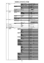
Page 4: ... 50 Hz Per Year kWh Year Protector Power Fuse Yes G 4 Regulation Safety CE EN60065 98 Radiation CE X Radiation G 5 Temperature Operation 5oC 40oC Storage 20oC 60oC G 6 Operating Humidity Less then 80 RH G 7 On Screen Menu Yes Display Menu Type Character Picture Yes Contrast Yes Brightness Yes Colour Yes Tint No Sharpness Yes Audio Yes Bass Yes Treble Yes Balance Yes BBE On Off Yes Stable Sound On ...

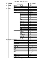
Page 5: ...ual On Off No Wide Yes Auto No Position Yes Fine Tuning No Fine Tuning No Tone 1 2 No T TEXT Keys TEXT MIX TV Yes CH Up Page Up Yes CH Down Page Down Yes Red Yes Green Yes Yellow Fine Tuning Yes Cyan Fine Tuning Yes F T B Expand Normal Yes Reveal Skip Yes Display Cancel Yes Reset Yes Reset Tone 1 2 No Hold Status Yes Sub Page Quick View Yes G 11 Features Auto Degauss Yes Auto Shut Off Yes Canal No...

Page 6: ...ector No Degauss No Main Power SW No Indicator Power No Stand by Yes On Timer No Terminals Front Video Input No Audio Input No Other Terminal No Rear Video Input Rear1 No Video Input Rear2 No Audio Input Rear1 No Audio Input Rear2 No Video Output No Audio Output No Euro Scart 21Pin Yes x2 Component Input No Diversity No Ext Speaker No DC Jack 12V Center No VHF UHF Antenna Input D Type AC Outlet No...

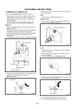
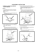
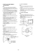
Page 7: ...ip up the sides of the Rubber Cap in the direction of the arrow and remove one side of the support Refer to Fig 1 2 2 DISASSEMBLY INSTRUCTIONS GND on the CRT Screwdriver Alligator Clip Support CRT GND on the CRT Rubber Cap CRT Support Fig 1 1 Fig 1 2 3 After one side is removed pull in the opposite direction to remove the other NOTE Take care not to damage the Rubber Cap INSTALLATION 1 Clean the s...

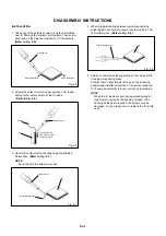
Page 8: ...using a blower type IC desoldering machine Refer to Fig 2 2 2 Fig 2 2 NOTE Do not add the rotating and the back and forth directions force on the IC until IC can move back and forth easily after desoldering the IC leads completely When IC starts moving back and forth easily after desoldering completely pickup the corner of the IC using a tweezers and remove the IC by moving with the IC desoldering...

Page 9: ...2 8 Thin tip Soldering Iron NOTE When the IC leads are bent during soldering and or repairing do not repair the bending of leads If the bending of leads are repaired the pattern may be damaged So be always sure to replace the IC in this case Finally confirm the soldering status on four sides of the IC using a magnifying glass Confirm that no abnormality is found on the soldering position and insta...

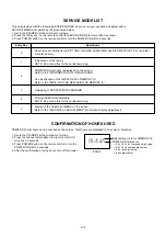
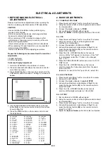
Page 10: ...ed on the screen Total hours are displayed in 16 system of notation 1 2 3 4 Set to the STANDBY at the minimum of volume Press the channel button 6 on the remote control for more than 3 seconds Press POWER button on the remote control to turn the POWER ON within 2 seconds After the confirmation of using hours turn off the power FIG 1 Initial setting content of MEMORY IC POWER ON total hours 16 x 16...

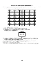
Page 11: ... is selected it will blink Again step through the DATA using VOL UP DOWN button until required DATA value has been selected Pressing ENTER will take you back to ADDRESS for further selection if necessary Repeat steps 4 to 7 until all data has been checked When satisfied correct DATA has been entered turn POWER off return to STANDBY MODE to finish DATA input Fig 1 Note No need setting for the posit...

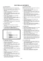
Page 12: ...et with Aging Test for more than 10 minutes Using the remote control set the brightness and contrast to normal position Connect the oscillator 39 5MHz to TP001 Activate the adjustment mode display of Fig 1 1 and press the channel button 13 on the remote control to select VCO COARSE Press the VOL UP DOWN button on the remote control until the OK appear on the screen If the OK is not displayed selec...

Page 13: ...n the remote control until the SHIFT quantity of the OVER SCAN on upside and downside becomes minimum 2 9 BRIGHT CENT 1 2 3 4 5 6 7 Place the set with Aging Test for more than 15 minutes Receive the black pattern RF Input Using the remote control set the brightness and contrast to normal position Activate the adjustment mode display of Fig 1 1 and press the channel button 17 on the remote control ...

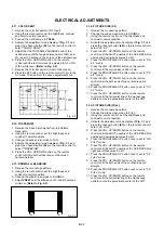
Page 14: ...until the horizontal line of the monoscope pattern comes to approximate center of the CRT 2 11 COLOR CENT 1 2 3 4 5 6 7 8 Receive the color bar pattern RF Input Using the remote control set the brightness contrast and color to normal position Connect the oscilloscope to TP804 Activate the adjustment mode display of Fig 1 1 and press the channel button 25 on the remote control to select COLOR CENT ...

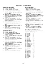
Page 15: ...e both ends of the vertical lines are straight Press the PROG PAGE UP button once to set to CC 14 9 mode Press the VOL UP DOWN button on the remote control until the horizontal line of the monoscope pattern comes to approximate center of the CRT 2 19 Confirmation of Fixed Value Step No Please check if the fixed values of the each adjustment items are set correctly referring below RF 00 00 00 45 00...

Page 16: ...fter performing adjustments in section 3 1 1 2 3 4 5 Receive the green raster pattern from color bar generator Adjust the pair of purity magnets to center the color on the screen Adjust the pair of purity magnets so the color at the ends are equally wide Move the deflection yoke backward to neck side slowly and stop it at the position when the whole screen is green Confirm red and blue colors Adju...

Page 17: ...MAJOR COMPONENTS LOCATION GUIDE D3 1 MAIN PCB CRT PCB CP101 TU001 IC201 VR601 J701 TP001 IC101 J801 TP804 SW501 VR501 FB401 FOCUS 1 VOLUME FOCUS 2 VOLUME SCREEN VOLUME T501 TP501 T402 POWER PCB ...

Page 18: ... 22 18 13 14 J701 21PIN x 2 71 72 18 4MHz NICAM DOLBY IC902 MSP3411G 3 2 I2C DATA CLK P CON 8V 39 12 11 65 13 66 P CON 5V AUDIO1 IN L R AUDIO2 IN L R 28 27 20 1 67 P CON 8V 12 14 7 2 5 10 SOUND 8V STEREO SOUND AMP IC1001 AN5277 BBE IC901 NJM2150AM AUDIO L R AUDIO L R DAF 3 11 RGB SCREEN FOCUS12 V OUT I2C DATA CLK 4 5 7 9 1 11 1 2 6 7 8 I2C DATA CLK I2C DATA CLK I2C DATA CLK 30V P CON 5V AGC TU001 ...

Page 19: ... R828 R829 R808 R804 R806 C813 B852 Q856 Q857 R881 R855 C854 R879 R878 B851 C865 C864 R877 R880 C860 C861 R872 D855 R869 R875 R871 D856 R868 R873 R874 R870 R867 C808 L801 L802 L803 L804 D858 D857 W093 B853 Q858 Q859 C821 J801_1 W895 W896 W897 C852 D854 D853 W096 Q855 W095 W094 D852 L853 L851 R889 Q852 Q853 W091 W090 C P 8 0 2 B C P 8 5 3 B L852 Q854 W009 W072 W081 W088 CP801B CP703B CP704B CP702B ...

Page 20: ...8 C102 C114 C128 C127 C126 C125 R114 R115 C109 C108 R131 R130 R129 R128 R120 R117 R103 R136 R116 R101 R107 IC102 R135 C120 R126 R132 R118 R133 R134 R127 C119 R108 R634 C636 C631 C632 C633 R627 R626 R631 R633 Q607 Q608 Q603 R636 Q605 R625 Q606 R615 R612 R616 Q711 R639 C205 Q604 R610 R623 R611 C201 R606 R604 R910 R124 R813 R810 C804 R817 R814 R812 C805 R819 R815 R811 C806R816 R809 R807 R886 C869 R86...

Page 21: ...R511 D507 W030 R463 D521 D410 R407 D417 W024 R418 R405 HS401 R428 C407 C423 R419 R465_1 W036 W037 D401 C428 D421 D418 D402 W019 CP703A CP702A W031 W048 W034 W043 W007 W871 R401 W025 TP501 W035 W008 RY501 HS501 W872 W046 Q404 C418 C506 C507 C535 D409 D505 D509 Q504 R529 D517 SW501 T401 D508 R527 R402 R464 W878 W879 C424 W002 D405 C417 L401 R448 W010 W011 D408 W889 W801 R460 W874 R503 W883 W884 T501...

Page 22: ...3 R519 R509 Q506 R528 R462 Q403 R433 R412 R415 R414 R461 R417 Q408 R459 R458 Q412 R535 R523 R515 R518 C529 R507 R539 R530 R191 R197 R439 R429 R470 R434 R472 R473 R195 C416 R454 R455 R471 R403 R404 R510 R406 R520 C405 R543 R538 SH501 C445 C436 C427 PRINTED CIRCUIT BOARDS POWER CHIP MOUNTED PARTS SOLDER SIDE F 7 F 8 ...

Page 23: ... 5 50 51 52 53 54 55 56 6 7 8 9 OF PRINTING AND SUBJECT TO CHANGE WITHOUT NOTICE NOTE THIS SCHEMATIC DIAGRAM IS THE LATEST AT THE TIME THE DC VOLTAGE AT EACH PART WAS MEASURED WITH THE DIGITAL TESTER WHEN THE COLOR BROADCAST WAS RECEIVED IN GOOD CONDITION AND PICTURE IS NORMAL NOTE S851Y S851X S852Y S852X S810Y NICAM_RESET DEGAUSS REMORT TUNER_BT A_MUTE BBE_H P FAIL SCL SDA STANDBYLED P CON 5V POW...

Page 24: ... B C301 0 01 B C306 0 022 B C203 0 022 B C637 100P CH C212 0 01 B C638 0 0047 B C631 0 01 B C632 180P CH C639 0 001 CH C640 0 1 B C633 220P CH C636 150P CH C602 1 50V KA C217 47 16V YK C213 1 50V KA C209 10 16V KA C220 470 10V YK C206 1 50V KA C605 1 50V KA C613 470 10V YK C611 3 3 50V KA C603 1 50V KA C604 1 50V KA C210 1 50V KA C607 1 50V KA C635 47 16V YK C628 100 6 3V YK C610 100 6 3V YK IC201...

Page 25: ...B D723 MTZJ12B D702 MTZJ6 8B D712 MTZJ12B W804 C709 100P CH C710 100P CH C721 100P CH C719 100P CH C761 0 01 B C720 470P CH C726 470P CH C727 470P CH C722 470P CH C729 0 01 B C730 0 01 B C716 100P CH C732 0 01 B C731 0 01 B C725 100 10V YK C724 10 16V KA C723 10 16V KA OF PRINTING AND SUBJECT TO CHANGE WITHOUT NOTICE NOTE THIS SCHEMATIC DIAGRAM IS THE LATEST AT THE TIME THE DC VOLTAGE AT EACH PART...

Page 26: ...1 50V KA C950 10 16V KA C949 10 16V KA C947 10 16V KA C920 10 16V KA C581 100 16V YK C582 220 10V YK C583 100 16V YK C584 220 6 3V YK C911 10 16V KA C939 3 3 50V KA C901_1 10 50V YK C936 10 16V KA OF PRINTING AND SUBJECT TO CHANGE WITHOUT NOTICE NOTE THIS SCHEMATIC DIAGRAM IS THE LATEST AT THE TIME THE DC VOLTAGE AT EACH PART WAS MEASURED WITH THE DIGITAL TESTER WHEN THE COLOR BROADCAST WAS RECEIV...

Page 27: ...R821 270 R809 56 R807 56 R888 1 2K 1 4W R874 68K 1 4W R873 68K 1 4W R816 56 R871 1 5K 1 4W R863 1 2K TP804 TP806 TP805 C854 10 160V YK C862 47 160V YK C864 10 160V YK C863 47 160V YK W896 W895 W897 W894 W898 W891 W813 W903 W902 W901 W899 L852 22uH L851 5 6uH L802 150uH 0607 L803 150uH 0607 L804 150uH 0607 L853 47uH D801 1SS133 D802 1SS133 D803 1SS133 D855 1SS133 D857 10ELS2N D852 1SS133 D853 1SS13...

Page 28: ...YK OF PRINTING AND SUBJECT TO CHANGE WITHOUT NOTICE NOTE THIS SCHEMATIC DIAGRAM IS THE LATEST AT THE TIME THE DC VOLTAGE AT EACH PART WAS MEASURED WITH THE DIGITAL TESTER WHEN THE COLOR BROADCAST WAS RECEIVED IN GOOD CONDITION AND PICTURE IS NORMAL NOTE L403 ELC16B501HN 1 2 3 L402 ELC18B501lN 1 2 3 L401 ELC16B222EN 1 2 3 L404_1 ELH5L6140N 1 2 3 CP852A B2013H02 5P 1 2 3 4 5 IC402 TLP521 1 SG SW 1 2...

Page 29: ... D501 RM11C EIC D504 RM11C EIC D517 RGP15J D503 RM11C EIC D512 11E1 EIC D525 11E1 EIC D511 1SS133 D527 1SS133 D509 RGP15J D505 RN_3Z Q505 KTC3198 RELAY SW Q509 KTC3198 FEED BACK SWITCHING C540 0 0022 2KV R C517_2 0 0022 2KV R C541 0 022 B C501 0 22 275V PHE840 C526 0 22 275V PHE840 C506 0 001 2KV B C529 0 01 B C528 0 01 B C507 0 001 2KV B C543 0 33 B C527 0 001 250V KX C513 0 01 B C516 470P 500V B...

Page 30: ...s div 0 5V 20µs div 7 9 1V 20µs div VIF SIF CHROMA 2V 5ms div 10 11 2V 20µs div 12 2V 20µs div 2V 20µs div 13 8 0 5V 20µs div 3 2V 20µs div 14 2V 20µs div 15 1V 20µs div NOTE The following waveforms were measured at the point of the corresponding balloon number in the schematic diagram H 1 ...

Page 31: ...div 23 200mV 10µs div 18 200mV 10µs div 19 1V 0 5ms div 24 100mV 0 5ms div 20 NOTE The following waveforms were measured at the point of the corresponding balloon number in the schematic diagram 25 1V 0 5ms div WAVEFORMS 26 1V 0 5ms div 27 1V 0 5ms div 28 0 5V 0 5ms div 29 200mV 0 5ms div 30 0 5V 0 5ms div H 2 ...

Page 32: ... div 33 50V 20µs div 34 5 0V 5ms div 52 50V 20µs div 35 NOTE The following waveforms were measured at the point of the corresponding balloon number in the schematic diagram 53 0 5kV 20µs div WAVEFORMS 54 2V 20µs div 55 10V 5ms div 56 200V 5ms div 57 200V 5ms div 58 5V 20µs div H 3 DEFLECTION ...

Page 33: ...117 120 V801 206 206 206 206 L503 PCB110 CRT PCB J801 117 101 108 109 110 112 112 113 203 116 203 116 203 119 119 119 119 203 SP1001 MECHANICAL EXPLODED VIEW I 1 ...

Page 34: ...MECHANICAL EXPLODED VIEW I 2 111 114 118 118 118 118 202 201 201 201 201 201 201 201 102 103 104 105 205 204 205 PCB010 MAIN PCB 106 107 204 204 204 205 205 205 PCB020 POWER PCB 115 SW501 FB401 ...

Page 35: ...5 735UPB0010 BUTTON POWER 116 761WPAA053 HOLDER PCB 117 762WPA0009 HOLDER CRT WIRE 118 800UQ00009 FELT SHEET 119 800UQ00010 FELT SHEET 120 8994101000 HOLDER CRT WIRE 201 8117540B04 SCREW TAPPING B0 TRUSS 4x20 202 8110630A44 SCREW TAP TITE P BRAZIER 3x14 203 8110630A04 SCREW TAP TITE P BRAZIER 3x10 204 8109I30A04 SCREW TAP TITE B WH7 3x10 205 8109630802 SCREW TAP TITE B BRAZIER 3x8 206 8111J50D04 S...

Page 36: ...P 0 12 UF 400V ECWF D603 D1VT001330 DIODE SILICON 1SS133T 77 C459 E5EZFD220M CE 22 UF 250V D604 D2WT011E10 DIODE SILICON 11E1 EIC C501 P2472B224M CMP 0 22UF 275V PHE840 D605 D1VT001330 DIODE SILICON 1SS133T 77 C504 E02LF5471M CE 470 UF 50V D606 D97U06R81B DIODE ZENER MTZJ6 8B T 77 C505 E52D0H221M CE 220 UF 400V D607 D97U06R81B DIODE ZENER MTZJ6 8B T 77 C506 C0JBB0713K CC 0 001 UF 2KV B D608 D97U06...

Page 37: ...530205016 SWITCH SDKVA30100 Q702 TAATA12660 TRANSISTOR SILICON KTA1266 AT Y GR VARIABLE RESISTORS Q703 T8YJ2412K0 TRANSISTOR SILICON 2SC2412KT146 R S VR501 V1163H2BTC VOLUME SEMI FIXED EVNCYAA03BE2 Q705 TPAAB05001 COMPOUND TRANSISTOR KRA102SRTK VR601 V1K63H4BTE VOLUME SEMI FIXED NVG6TLTAB223 or Q706 T8YJ2412K0 TRANSISTOR SILICON 2SC2412KT146 R S V1263H4BT7 VOLUME SEMI FIXED RH0683CJ4R Q707 TPAAB05...

Page 38: ...01 043228005R TRANSFORMER FLYBACK 3228005R FH501 06710T0006 HOLDER FUSE EYF 52BC FH502 06710T0006 HOLDER FUSE EYF 52BC OS101 077Q047001 REMOTE RECEIVER PIC 47143SY PH005 069W01001A CONNECTOR PCB SIDE 003P 2100 RY501 0560V20115 RELAY ALKS321 SP1001 070W547001 SPEAKER MSF 18D5SB10 02 TH501 D8E080A100 DEGAUSS ELEMENT B59209 J80 A10 TM101 07660DN050 TRANSMITTER SBKM00025A TU001 0144507026 TUNER UHF TU...

Page 39: ...d specifications are subject to change without notice COLOR TELEVISION RECEIVER WF70 3020 REVISION 1 MFR S VERSION B C B MFR S VERSION A C IC101 OECF001A OTP OECF001A MASK PRODUCT IMPROVEMENT ORIGINAL Change of HORIZONTAL SIZE ...

Page 40: ...of the vertical lines are straight Press the PROG PAGE UP button once to set to CC 4 3 mode Press the VOL UP DOWN button on the remote control until the horizontal line of the monoscope pattern comes to approximate center of the CRT M3K8 02G U1Y3543 SPEC NO O R NO Change of HORIZONTAL SIZE ELECTRICAL REPLACEMENT PARTS LIST REF NO MFR S VERSION A MFR S VERSION B PART NO DESCRIPTION L402 02D1000001 ...

Reviews: