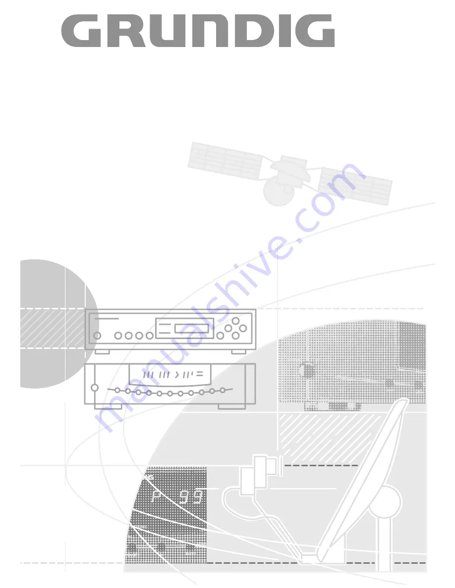
S AT E L L I T E T V R E C E I V E R
S T R 3 2 2 T W I N
+ A n t e n n a - P o s i t i o n e r
S T R 4 0 0 A P
Page 1: ...SATELLITE TV RECEIVER STR 322 TWIN SATELLITE TV RECEIVER Antenna Positioner STR 400 AP...
Page 2: ...16 Contents Buttons and their Functions on the Receiver General 17 P F Selecting Programme Frequency 17 V H Selecting Vertical Horizontal Polarisation and Input A B 18 VIDEO Adjusting the Video Devia...
Page 3: ...and or aerial lead During a thunderstorm you should therefore always dis connect the mains and aerial plugs Protect Your Environment Attention Do not throw used batteries from the remote control hands...
Page 4: ...ON OFF INPUT SAT L 36V 2 5A 0 12V 0 1A AGC GND 5V 0 2A POL MAGN GND M2 M1 LNC LN C LN C MAG POL A OMT 11 GHz 12 5 GHz A xxxxxxxxxxxxxxxxxxx B 1 2 3 4 5 6 7 8 9 10 DC OUT 15V 0 8A Magn polarizer 45 sk...
Page 5: ...is automatically swit ched via the SAT receiver to the TV receiver also in stand by To 1 and 2 If a decoder is connected this is automatically switched on evaluation of the switching voltage On decod...
Page 6: ...transmission frequency e g 11325 MHz MHz indication In audio mode direct entry of the sound carrier frequency e g 7 02 MHz Timer programming Entry of date start and stop time Switching the receiver o...
Page 7: ...ntrol handset can also be used for important functions of units of other manufacturers 9 b Switches the receiver to standby Only possible via the remote control handset I Press together with the 8 but...
Page 8: ...ion q Downward step by step selection of programme positions and all adjustable data 3 2 1 q MEMORY Storage of all preset data qQ Upward step by step selection of programme positions and all adjustabl...
Page 9: ...n Designation Connection 11 0 12 V 0 1 A Switching voltage output for LNC switching relay etc 12 AGC Field strength measuring output for precise aerial adjustment 13 GND Earth ground 14 5 V 0 2 A Outp...
Page 10: ...more than 3 seconds Selecting the Aerial Input The receiver is provided with two aerial inputs Preprogram ming in the factory has been made for the standard solution comprising one LNC with frequency...
Page 11: ...the west can be restricted by limit switches inside the motor or by mechanical end stops This is especially necessary to protect the aerial from running against obstructions walls trees etc In additio...
Page 12: ...down the button until the aerial has reached its west end stop The display indicates Press the button to let run the aerial approx 20 impul ses to the east then store the setting with the MEMORY butto...
Page 13: ...waveguide filter Polarization switching with 14 18 V or motor driven magnetic polarizer Frequency Polarization LNC power Preprogrammed Preprogrammed Switching frequency range skew value switching vol...
Page 14: ...th buttons MODE MODE with buttons e g with buttons e g MODE then change frequency with buttons MODE with buttons e g MODE then change frequency with buttons MODE MEMORY MEMORY store in memory and stor...
Page 15: ...en the inputs then is per formed automatically Adapting the Polarizer If you should have selected a system with magnetic or motor driven polarizer this must also be preadjusted as there are many diffe...
Page 16: ...32 STEREO SIGNAL IIIIIIIIIIIII Adjust the optimum skew value as explained above press the MODE button once again and store the setting with the MEMORY button From this point on all programme positions...
Page 17: ...an additional 0 must be entered at the first position TIMER o p I99 X1____Mz STEREO SIGNAL IIIIIIIIIIIII General As already stated the receiver has been preprogrammed at the factory for the main prog...
Page 18: ...GHz LNC s the video signal must be inverted by selecting the set ting DEV 1 DEV 3 TIMER o p I99 DEV X3XX STEREO SIGNAL IIIIIIIIIIIII TIMER o p I99 H1X18VX STEREO SIGNAL IIIIIIIIIIIII AUDIO Mono Stereo...
Page 19: ...II You can allocate a value between 99 East and 99 West by means of the or button In this way you can allo cate the satellite position the number of degrees at which the satellite stands in the orbit...
Page 20: ...rn to programme position RADIO Selecting Radio Mode Pressing the RADIO button toggles between SAT TV and radio mode The unit automatically switches to the last selec ted programme position Last Statio...
Page 21: ...TIVE programme position MODE COPY see above A detailed explanation of the menu functions of the Mode menu is given in the following sections The menu has a loop structure the menu options COPY at the...
Page 22: ...carrier frequency with the buttons or the numeric buttons on the remote con trol handset Conclude by storing the setting with the MEMORY button For stereo reception only the lower sound carrier for t...
Page 23: ...n the display It is possible to switch the decoder into the signal path and to select between AUTOMAT and ON by means of the buttons Select AUTOMAT for decoders which deliver a switching voltage when...
Page 24: ...d depends on the used LNC Necessary picture and sound corrections such as for exam ple sorting copying sound carrier and mono stereo chan ges must be carried out now not during the ATS search fun ctio...
Page 25: ...pprox 3 seconds The receiver is unlocked and the security code cleared Remember your personal code number If you should forget your personal code number the key on the last page cover will help you Wi...
Page 26: ...switch to the other level Through simultaneously pressing the 8 button on the remote control handset and one of its other command but tons you can switch to the second command level of the remote cont...
Page 27: ...mbers on the pic ture screen by holding down the VIDEO Z button and pressing in addition the 3 button Example Basic setting The display indicates one after the other 30 means GRUNDIG video recorder IR...
Page 28: ...IIIII Entering a programme Enter the number of the desired programme directly with the numeric buttons on the remote control handset for example 182 The display indicates If you wish to preprogramme a...
Page 29: ...the corresponding pro gramme is switched on The symbol for the active Timer is flashing e g 1 with Timer 1 At the same time a switching voltage is output on the EURO AV VCR socket Correspondingly equi...
Page 30: ...8 V max 800 mA LNC voltage with superimposed 22 kHz switching signal selectable If necessary the LNC voltage can be switched off with switch wI Connections 10 pole connector strip for controlling the...
Page 31: ...mp fuse either in the plug or at the distribution board Important The wires in the mains lead are coloured in accordance with the following code BLUE NEUTRAL BROWN LIVE As the colours of the wires in...
Page 32: ...GRUNDIG AG D 90762 F RTH Printed in Germany 4 10 M 1 2 3 4 5 6 7 8 9 21107 941 63...