background image

- 15 -

- 15 -

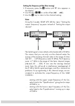
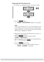
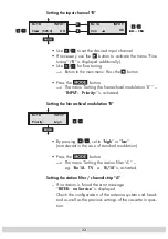
Setting the frequency offset (fine tuning)

• If necessary press the 

 button until “

0

” also appears in 

the display. 

• Use the keys 

 to set the offset (

-64

 … 

+64

).

• Use the 


/

 key to return to the channel setting.


Note:

  Using the Cassette HDMT 473 MX the menu “Setting the 

output  frequency” appears instead of “Setting the output 
channel”.

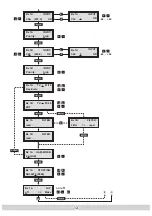
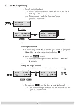
Bx 1A

112.00 MHz

OUTPUT:

Bx 1A

 MUX  7  / 

MTP15

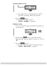
VERSION:

Bx 1A

Modulator: on

OUTPUT:

/

+

/

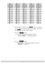
  The QAM signal is transmitted with a bandwidth of 8 MHz. 

This means that you can only use the channel centre fre-
quency of the existing channel raster in the range of chan-
nels S21 … C69 (frequency raster 8 MHz). The frequency 
raster is 7 MHz in the range of the lower channel ranges 
(channels S2 … S20). If one uses the existing channel 
raster here, this will result in interference (overlapping) of 
the 8 MHz QAM signal packages and thus transmission 
problems. For programming in this channel range, we rec-
ommend to calculate the output frequency of the QAM 
modulator, 

…   starting with the upper output frequency of the Cas-

sette listed in the “Specifications” going back in steps 
of 8 MHz, or 

…   starting with the lower output frequency of the Cas-

sette listed in the “Specifications” moving up in steps 
of 8 MHz. 

Summary of Contents for GSS HDMT 473 MX

Page 1: ...er Stra e 43 D 90471 Nuremberg Phone 49 0 911 703 8877 Fax 49 0 911 703 9210 Email info gss tv Internet http www gss tv Grundig SAT SystEms Assembly Instructions Assembly Instructions English HDMT 473...

Page 2: ...11 5 1 Preparation 11 5 2 The menus at a glance 12 5 3 Cassette programming 14 Selecting the Cassette 14 Setting the output channel 14 Querying software versions 17 Modulator settings 17 Setting outpu...

Page 3: ...re the device is adequately ventilated Do not cover the ventilation slots Beware of short circuits No liability is accepted for damage caused by faulty connection or inexpert handling Observe the rele...

Page 4: ...dB V 16 QAM 2 3 GI 1 4 8k HF output HDMT 473 MX Frequency range 112 MHz 306 MHz HDMT 474 MX Channels S21 S41 Frequency range 306 MHz 466 MHz Channel raster 8 MHz HDMT 475 MX Channels C21 C69 Frequency...

Page 5: ...lows to create a new data flow out of the stations selected individually from the two data flows The prepared input signals are transmitted to the HF output collector of the head end via the HF output...

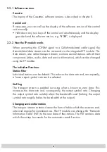
Page 6: ...nd service information which can be changed using the TP module The individual functions Station filter Individual stations can be deleted This reduces the data rate and consequently a lower output sy...

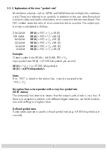
Page 7: ...AM SR A FEC x 2 5 x SR E 16 QAM SR A FEC x 1 2 x SR E 4 QAM SR A FEC x 1 1 x SR E Example Output symbol rate SR A 64 QAM FEC 3 4 Input symbol rate SR E 27 500 kilosymbols per second SR A 3 4 x 1 3 x 2...

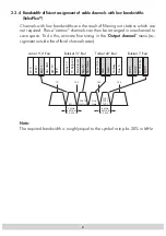
Page 8: ...ng in the Output channel menu as signment outside the official channel raster Note The required bandwidth is roughly equal to the symbol rate plus 20 in MHz ESC 1 Nile TV Nile News TVP 1 TVP 2 TVP 3 V...

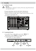
Page 9: ...y make it contact with the connections of the circuit board and the HF bus bar Fasten the Cassette with the 1 screws 3 2 Connecting the Cassette Connect the HF input cable with the input sockets INPUT...

Page 10: ...unit then shows the menus You can select the following main menu items with the button Cassette Output channel Input channel Bx A Bx B Hierarchical modulation Bx A Bx B Station filter Bx A Bx B QAM m...

Page 11: ...arrier frequency of the channel In this way the Cassette s level can also be set with an analogue TV test receiver set to the video carrier frequency of the channel In order to prevent interference wi...

Page 12: ...EL CONTROL OUTPUT Bx 1A Modulator OUTPUT on on off berwachung KDG Monitoring KDG Bx 1A MODE Ueberwachung 64 64 Bx 1A MUX 7 MTP15 VERSION Bx 1A S21 OUTPUT 306 00 Bx 1A C5 12 S3 24 TWIN SAT C07 B x 4 C5...

Page 13: ...PUT OK Bx 1B Priority INPUT high Bx 1A C40 0 INPUT OK Bx 1A C34 0 INPUT OK 64 64 64 64 Bx 1A read FILTER Bx 1B read FILTER Bx 1A SR 6875 5800 STUFFING Bx 1B Filter read FILTER Bx 1A off NIT Make M Bx...

Page 14: ...ng the output channel By pressing set the desired output channel The channel range that can be set depends on the type of Cassette used Bx 1A C5 12 S3 24 TWIN SAT C07 B x 4 C5 12 S3 24 TWIN SAT C07 Bo...

Page 15: ...el centre fre quency of the existing channel raster in the range of chan nels S21 C69 frequency raster 8 MHz The frequency raster is 7 MHz in the range of the lower channel ranges channels S2 S20 If o...

Page 16: ...00 C 38 610 00 C 39 618 00 C 40 626 00 C 41 634 00 Channel Channel centre frequency MHz C 42 642 00 C 43 650 00 C 44 658 00 C 45 666 00 C 46 674 00 C 47 682 00 C 48 690 00 C 49 698 00 C 50 706 00 C 51...

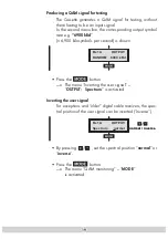
Page 17: ...ettings If you do not need the output channel of this modulator you can switch it off By pressing the buttons switch the modulator HF output on default setting if necessary or switch it off Press the...

Page 18: ...can measure the absolute output level using an analogue test receiver Measure the output level of the channel strip using the con nected antenna test receiver Press the AUDIO button to activate the m...

Page 19: ...e menu Inverting the user signal OUTPUT Spectrum is activated Inverting the user signal For exceptions and older digital cable receivers the spec tral position of the user signal can be inverted inver...

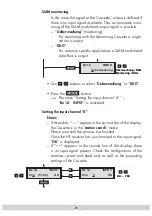
Page 20: ...INPUT is activated Setting the input channel A Notes If three dots appear in the second line of the display the Cassette is in the station search mode Please wait until the process has finished Once...

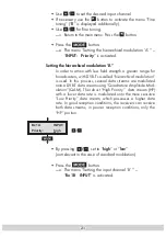
Page 21: ...l modulation is used In this process several data streams are modulated onto a DVB T data stream using Quadrature Amplitude Mod ulation QAM The robust High Priority data stream HP with a lower data ra...

Page 22: ...pressing set to high or low not relevant in the case of standard modulation Press the button The menu Setting the station filter A e g Bx 1A TV 01 18 is activated Setting the station filter channel st...

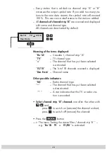
Page 23: ...rip A TV TV channel type The channel that has just been selected is activated 01 18 The 1st of 18 channels scanned is displayed Das Erste Channel name Other possible indicators RA Radio channel type T...

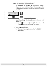
Page 24: ...meaning of what is displayed is equivalent to the description for channel strip A Select channel strip B channels one after the other with and press to switch on activate the channel wished press to s...

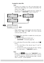
Page 25: ...button The menu Setting the QAM mode QAM MODE is activated page 26 To scan the data of the station filters manually press the button The station filters of the channel strips A and B are scanned As so...

Page 26: ...ss the button The menu Setting the stuffing STUFFING is activated Setting the stuffing SR 6875 number 1 Active output symbol rate Bx 1A SR 6875 5800 STUFFING Number 1 Number 2 5800 number 2 The curren...

Page 27: ...y value up to 7 000 Reduce the value of number 1 With the station filter switched on the number 1 can be decreased To do this observe the number 2 for 30 seconds and note the highest value Add rough l...

Page 28: ...ll QAM Cas settes in the NIT menu changes to on To deactivate the new NIT Press the button The original NIT is restored Notes The cable NITs of the other Cassettes remain acti vated When it is reactiv...

Page 29: ...he Cassette A page 14 The new settings are saved permanently If functions of the TP module are activated their sta tus is shown in the second line of the display M station filter on S Stuffing is acti...

Page 30: ...Alterations reserved Technical data E O E by GSS GmbH 03082006 Service Phone 49 0 911 703 2221 Fax 49 0 911 703 2326 Email service gss tv...

Reviews: