GRUNDIG Service
Xenaro – GDP 42…
3 - 5
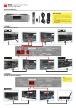
Steckerübersicht / Connection Overview
1. Main Board
1.1 Socket J11 to Power Supply
Pin
Lever (ca.)
Name
Description
1
+5V
+5V
An5 Volts out
2
0V
AGND
Analogue Ground
3
+12V
+12V
An12 Volts out
4
0V
AGND
Analogue Ground
5
-12V
-12V
Analogue -12 Volts out
6
0V
GND
Analogue Ground
7
+3.3V
+3.3V
+3.3 Volts out
8
+3.3V
+3.3V
+3.3 Volts out
9
0V
GND
Digital Ground
10
0V
GND
Digital Ground
11
+5V
+5V
+5 Volts out
12
M+8V
M+8V
M+8 Volts out
13
0V
GND
Digital Ground
14
-20V
-20V
-20 Volts out
1.2 Socket J17 to FP3001 Key Control Board (R)
Pin
Lever (ca.)
Name
Description
1
+5V
WAKEUP
WAKEUP
2
+5V
CS
Chip select
3
+5V
CLK
Clock
4
0V
GND
Ground
5
+5V
DATAOUT
Data out
6
+3.3V
DATAIN
Data in
7
0V
GND
Ground
8
+5V
+5V
+5 Volts out
9
IR
IR
Remote Control data in
10
-20V
-20V
-20 Volts out
1.3 Socket J19 to DVD Drive
Pin
Lever (ca.)
Name
Description
Play DVD/CD
no Disc
1
0V
0V
AGND
Analogue Ground
2
0V (DVD)
3.3V
HFMON
Dual Laser Control
3.3V (CD)
3
0V
0V
GAINH-L
Laser Beam Control
4
0V
0V
AGND
Analogue Ground
5
1.2V
1.65V
FBAL
Focus Balance
6
1.6V
1.65V
TBAL
Tracking Balance
7
0V
0V
AGND
Analogue Ground
8
3.3V
3.3V
FEPENB
Frontend Enable
9
0V
2.7V
FEPCLK
Frontend Clock
10
0V
2.7V
FEPDATA
Frontend Data
11
0V
3.3V
OFTR
Out of Track
12
0V
0V
BDO
Drop Out Signal
13
0V
0V
AGND
Analogue Ground
14
1.65V
1.65V
TE
Tracking Error
15
1.65V
1.65V
FE
Focus Error
16
2.2V
1.65V
FS
RF Amplifier Signal
17
1.65V
1.65V
VHALF
Reference Voltage
18
3.3V
3.3V
A+3.3V
An3.3V
19
3.3V
3.3V
A+3.3V
An3.3V
20
0V
0V
AGND
Analogue Ground
21
1.8V
1.8V
ARF
RF Amplifier Signal
22
1.8V
1.8V
NARF
RF Amplifier Signal
23
1V
1V
TSTSG
Test Signal
24
1V
1.6V
RFENV
RF Envelope
25
5V
5V
A+5V
An5V
26
2.2V
2.2V
VREF2
Reference Voltage
27
2.2V
2.5V
LDCUR
Loader Current
28
3.3V
3.3V
IN-SW
Tray End Position Switch
29
3.3V
3.3V
TRAY-TRV
Motor Control Sledge/Tray
30
3.3V
2.7V
MUTE3
Motor Control Disc
31
1.65V
1.65V
TRVSIN
Motor Control Sledge/Tray
32
1.65V
1.65V
TRAYREF
Motor Reference Sledge/Tray
33
1.65V
1.65V
TRAYIN
Motor Control Sledge/Tray
34
1.65V
1.65V
SPDIN
Motor Disc Speed Control
35
1.65V
1.65V
TRIN
Tracking Control
36
1.65V
1.65V
FOIN
Focus Control
37
2V
1.65V
DMV
Disc Motor Voltage
38
0V
2.4V
MUTE4
Motor Control Sledge/Tray
39
3.3V
0V
MUTE12
Focus/Track Control
40
0V
0V
MGND
Motor Ground
41
0V
0V
MGND
Motor Ground
42
0V
0V
MGND
Motor Ground
43
0V
0V
MGND
Motor Ground
44
9V
9V
M+9V
Motor +9V
45
9V
9V
M+9V
Motor +9V
46
9V
9V
M+9V
Motor +9V
47
5V
5V
D+5V
D5V
48
5V
5V
D+5V
D5V
49
0V
0V
DGND
Digital Ground
50
0V
0V
DGND
Digital Ground
1.4 Socket J7 (TV SCART)
Pin
Lever (ca.)
Name
Description
1
2Vrms/10K
Ω
TV_AOR
Audio Out Right
2
3
2Vrms/10K
Ω
TV_AOL
Audio out Left
4
0V
GND
Ground
5
0V
GND
Ground
6
7
700mVpp
TV_BLUE_O
BLUE Out
8
+6V/+12V
TV_PIN8
Control
9
0V
GND
Ground
10
11
700mVpp
TV_GREEN_O
GREEN Out
12
13
0V
GND
Ground
14
0V
GND
Ground
15
700mVpp
TV_RED_O
RED Out
16
3.3V
TV_PIN16_O
Blank
17
0V
GND
Ground
18
0V
GND
Ground
19
1.0Vpp
TV_CVBS_O
Composite Video Out
20
21
0V
GND
Ground
1.5 Socket J3 (AUDIO OUT)
Pin
Lever (ca.)
Name
Description
1
2Vrms/10K
Ω
TV_AOL
Audio Out Left
2
2Vrms/10K
Ω
TV_AOR
Audio out Right
3
0V
GND
Ground
1.6 Socket J4 (Electrical SPDIF)
Pin
Lever (ca.)
Name
Description
1
1.8V
SPDIF_COAX_O
Digital Audio Out
2
0V
GND
Ground
1.7 Socket J5 (Optical SPDIF)
Pin
Lever (ca.)
Name
Description
1
1.8V
SPDIF_OPTIC_O
Digital Audio Out
2
5V
5V
VCC
3
0V
GND
Ground
1.8 Socket J6 (CVBS+S Video)
Pin
Lever (ca.)
Name
Description
1
0V
GND
Ground
2
0V
GND
Ground
3
0V
GND
Ground
4
1 Vpp
Y
5
0.6Vpp
C
6
0V
GND
7
1Vpp
TV_CVBS_O
Composite Video Out
8
0V
GND
Ground
9
0V
GND
Ground
Hinweis:
1. Audio-Signal: 1KHz, 0dB.
2. Video-Signal: 100% Farbbalken
3. Video-Signale sind mit Oszilloskop gemesse (Spitze-Spitze-Werte);
Audio-Signale sind mit Millivoltmeter gemessen (Effektiv-Werte)
Restliche Pegel sind mit Digital-Voltmeter gemessen.
4. Die angegebenen Werte sind Annäherungswerte.
Note:
1. Audio test signal is 1KHz, 0dB.
2. Video test signal is 100% color bar signal.
3. Video signal’s measuring equipment (peak-to-peak value) is oscilloscope;
Audio signal’s measuring equipment (rms value) is millvoltmeter;
Other signal’s measuring equipment is digital multimeter.
4. The measured values given in the above forms are approximates!