background image

Partie générale / General Section

CUC 2058 F / 2059 F

2

GRUNDIG Service

II y a lieu d'observer les recommandations et les
prescriptions de sécurité de I'Instruction de Ser-
vice "Sécurité" Réf. N

°

 72010 800 0000 ainsi

que les prescriptions spécifiques à chaque pays!

The regulations and safety instructions shall be
valid as provided by the "Safety" Service Manual,
part number 72010 800 0000, as well as the
respective national deviations.

Table of Contents

Page

Module List ...................................................................................... 3
Technical Data ................................................................................ 4
List of Modules – Service Manual with Supplements ...................... 5
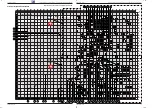
Chassis Board ................................................................................. 6
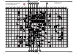
Chassis Board (enlarged) Detail 1 ................................................ 13
Chassis Board (enlarged) Detail 2 ................................................ 15
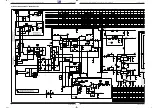
Mains Chassis ............................................................................... 17
Signal Chassis A ........................................................................... 21
Signal Chassis B ........................................................................... 25
Processor Board 29305 219 0700 ................................................ 28
CRT Panel 29305 122 2500 ......................................................... 30
Panorama View 29305 129 0400 .................................................. 32
Spare Parts Lists ........................................................................... 33

General Section

You can order these test equipments from the Service organization or
at the address mentioned below. We refer to you that part of these test
equipments is already obtainable on the market.

Grundig France
5, Bld Marcel Pourtout
92563 RUEIL MALMAISON Cedex
Tel. 01 41 39 26 26, Telefax 01 47 08 69 48
eMail: [email protected]
Internet: http://www.grundig-instruments.de

Sommaire

Page

Composition des appareils .............................................................. 3
Caractéristiques  techniques ........................................................... 4
Tableau des modules – Service Manual avec suppléments ........... 5
C.I. principal .................................................................................... 6
C.I. principal (agrandi) dessin de détail 1 ...................................... 13
C.I. principal (agrandi) dessin de détail 2 ...................................... 15
C.I. châssis-alimentation ............................................................... 17
C.I. du signal A .............................................................................. 21
C.I. du signal B .............................................................................. 25
C.I. du processeur 29305 219 0700 .............................................. 28
C.I. tube 29305 122 2500 ............................................................. 30
Vue Panoramique 29305 129 0400 .............................................. 32
Liste de pièces détachées ............................................................ 33

Partie générale

Ces auxiliaires de maintenance peuvent être obtenus auprès des
Stations Techniques Régionales Grundig ou à l'adresse ci-dessous.
Une partie de ces auxiliaires de maintenance est disponible dans le
commerce.

Grundig France
5, Bld Marcel Pourtout
92563 RUEIL MALMAISON Cedex
Tel. 01 41 39 26 26, Telefax 01 47 08 69 48
eMail: [email protected]
Internet: http://www.grundig-instruments.de

GB

The Service Manual CUC 2030 F / CUC 2031 F applies to the colour
television receivers specified on the front page. This Manual describes the
differences and the additionally fitted modules of the TV receivers.
The individual modules and the relevant part numbers are listed in the
tables on page 3 and 5.
Basic instructions for servicing are given in the:
– Service Manual CUC 2030 F / 2031 F (Part No. 72010 020 8000)
– 2 nd Supplement CUC 2080 F (Part No. 72010 020 8200)
– Safety Instructions (Part No. 72010 800 0000)

Pour les appareils présentés sur la première page, se reporter au
manuel d'utilisation CUC 2030 F / 2031 F. Ce supplément contient les
différences ainsi que les équipements complémentaires des appareils.
La liste des modules et des numéros de référence est indiquée sur le
tableau de la page 3 et 5.
Les documents de base pour la maintenance sont:
– Service Manual CUC 2030 F / 2031 F (Réf. N

°

 72010 020 8000)

– Supplément N

°

 2 CUC 2080 F (Réf. N

°

 72010 020 8200)

– Prescriptions de Sécurité (Réf. N

°

 72010 800 0000)

Dans le cadre de changements informatiques importants, les
références des pièces détachées passent de 10 à 12 chiffres.

Exemple:

Auparavant: 29504-111.22
Maintenant:

29504 111 2200

Pendant la période de transition, les deux formes d’écriture
pourront apparaître dans les instructions de service.

Liste de pièces détachées

Les numéros à quatre chiffres de désignation de la pièce détachée font
référence aux quatre derniers chiffres des références des châssis ou
des modules.

Exemple:

3100

^

=

29704 004 3100

Due to the conversion of the EDP system, the previous 10-digit part
numbers were change to 12-digit numbers.

Example:

previous:

29504-111.22

new:

29504 111 2200

During the conversion of the system, either form may be found in
the Service Manual.

Spare Parts Lists

The set off four figures in the designation of the spare parts refer
to the four figures at the end of the part numbers of the chassis or
modules.

Example:

3100

^

=

29704 004 3100.

F

Summary of Contents for CUC 2058F

Page 1: ...maintenance Additionally required Service Documents for the Complete Service Btx 32700 R f N Part Number 72010 020 8400 Sous r serve de modifications Subject to alteration Printed in Germany VK24 0299...

Page 2: ...3 RUEIL MALMAISON Cedex Tel 01 41 39 26 26 Telefax 01 47 08 69 48 eMail instruments grundig de Internet http www grundig instruments de GB The Service Manual CUC 2030 F CUC 2031 F applies to the colou...

Page 3: ...8 1987 MINISTERO P T N MADE IN AUSTRIA FABRICANTE GRUNDIG AG WIEN 25kV BESCHLEUNIGUNGSSPANNUNG MAX 25kV 1 0mA RADIOL GICA TENSI N DE ACELERACI N M X 25kV 1 0mA PROTEGGERE L APPARECCHIO DALL UMIDITA AT...

Page 4: ...Casque Headphones Entr e vid o Video IN 1 x Cinch 1 x Cinch Entr e audio Audio IN 2 x Cinch 2 x Cinch Connexions au dos Connections Rear Panel Euro AV 1 noire black Entr e sortie FBAS Entr e SBAS Entr...

Page 5: ...Socket Board 29305 008 3700 Page 3 30 C I Tube CRT Panel 29305 122 1600 Page 3 11 29305 122 2100 Page 35 29305 122 2500 Page 30 C I additionnel p C I Couleur Subpanel for Colour Module 29305 119 4200...

Page 6: ...203 C31046 159 193 C32021 120 175 C32023 61 111 C32024 60 96 C32108 135 98 C32327 46 207 C32332 54 206 C32334 57 121 C32343 24 210 C32346 31 210 C32360 37 208 C32364 60 210 C32423 112 175 C33019 156 1...

Page 7: ...inates X Y Pos N Coordonn es Pos No Coordinates X Y Pos N Coordonn es Pos No Coordinates X Y Chassis Board Coordinates of the components on the Solder Side Bottom Side Circuit principal Coordonn es de...

Page 8: ...1 4 5 8 IC82005 1 4 5 8 IC82000 3 1 IC80000 R60037 R61313 D57023 D52001 D50014 D60037 D60005 D81501 D60013 D57101 D57013 D81012 D57011 D57122 D50016 D57012 D40064 1 56 29 28 IC34015 F32121 F33025 F321...

Page 9: ...R40046 _CR40056 CR40062 CR41011 CR33019 CR34041 CR34067 _CR32157 CR32101 CR32110 CR52252 CR32104 CR32412 CR57002 CR31009 CR46001 CR81004 CR43265 CR34076 CR32416 CR57116 CR31047 CR31003 CR82001 CR81006...

Page 10: ...R31008 CR40061 _CR40048 CR40046 _CR40056 CR40062 CR41011 CR34067 _CR32157 CR32101 CR32110 CR32104 CR31009 CR46001 CR81004 CR34076 CR82001 CR81006 CR81008 CR81084 CR81501 CR61044 CR61054 CR81011 CR8107...

Page 11: ...9 CR43181 CR43058 CR43184 CR43077 CR43046 CR43095 CR43276 CR43041 CR43043 CR43183 CR43182 CR43048 CR43061 _CR32439 _CR32433 _CR34071 CR31044 CR31045 _CR32436 CR32420 CR31046 CR81072 CR31006 CR32432 CR...

Page 12: ...7 82cm 16 9 PHI CUC 2035 40 63 70cm PHI DPL 70cm 16 9 PHI 825 97 82 330u 220 220 82cm 16 9 VC 70cm 16 9 VC CUC 2059 70cm 16 9 CUC 2058 82cm 16 9 CUC 2033 CUC 2032 63 70cm PHI VC SER250 6 8k BYT56M 120...

Page 13: ...110 95 110 95 0 22u 0 2u 8 2k 8 2k 8 2k 8 2k 8 2k 8 2k 8 2k 8 2k ZY33 ZY33 ZY33 ZY33 ZY33 ZY33 ZY33 ZY33 BR55008 5 6 5 6 5 6 5 6 5 6 5 6 5 6 5 6 R55003 0 1u 2 7k 2 200 011 R62505 TABELLE 2 60023 C1500...

Page 14: ...5 4 3 2 1 IC82005 VCC SDA SCL A0 A1 A2 VSS TEST 8 7 6 5 4 3 2 1 X24C08 IC82000 U AFC U TUN U AFC U TUN 1 2 3 4 5 6 7 8 9 10 11 12 13 14 15 ST SB Q80001 18 432MHz Q32305 L46021 8 2uH L31043 _BR31041 1...

Page 15: ...E A 6 5 4 3 2 1 9 8 7 ST NF2 8 2 _R40014 BR43061 3 3k CR32319 82 R32359 3 2 1 ST H MC14551 1 16 15 14 13 12 11 10 9 8 7 6 5 4 3 2 MC14551 CIC43050 IND2 MONO n V 3 3k CR32318 560p CC32322 10n CC32321 I...

Page 16: ...R G B SW SSC CHROMA SDA1 SCL1 FBAS SDA SCL n V 27k CR34054 M R57011 U AFC 4 43MHz Q34043 3 58MHz Q34044 6 5 4 3 2 1 7 ST PIP2 5 4 3 2 1 ST PIP1 INL n V MONO MONO E 27k CR34053 INL U U M M M M 1N4148 D...

Page 17: ...56 470 470 680 470 680 470 560 CR32101 820 560 820 560 119 42 119 45 2031 2031 2051 2051 470k 470k 470k 470k 470k 470k 1M 1M 1M 2080 VC TDA8844N2 LOR VIDEOCOLOR 2030 2030 2030 2030 2030 OPTIONSLIST CU...

Page 18: ...6 26 29 29 161098 PART A 61 63 64 65 66 70 71 72 74 76 29305 119 39 46 47 48 54 56 57 58 59 60 29305 119 37 40 75 VARIANTE 1 0 VARIANTE 1 1 28 14 20 1 10 9 8 7 6 5 4 3 11 12 13 15 16 17 18 19 22 25 26...

Page 19: ...CR80914 CR80913 CR80916 CR80911 CR80917 CR80912 20 1 60 40 CBR80925 CBR80921 CBR80924 CBR80926 CBR80923 CBR80922 CC80911 CC80917 CC80918 CC80913 CC80921 CC80901 CC80912 CC80903 CC80904 CC80915 CC80914...

Page 20: ...68k R24003 1 8k R24072 8V 8V 8V 1 1 1 1 M M M M M M M M M C C V V V V V V V V V V V V 230998 91 BILDROHRPLATTE 29305 122 21 70cm 16 9 PHI 72cm PHI R24082 01 18 18 122 25 84cm VC NUR BEI 122 23 25 150k...

Page 21: ...UG C21502 1 7 RGB 1 2 ST DF1 1 5 ST BR R21512 R21503 D21502 C24081 10 9 8 11 1 12 4 3 2 7 6 5 C24021 E C T22023 4 5 6 7 8 9 10 11 12 R24022 R21511 29304 722 43 4B 01 BILDROHRPLATTE 3 2 1 5 6 4 zum Foc...

Page 22: ...1 2 4 5 CNY17 G OK64103 DF2 56k R64109 4 7k R64102 220k R64104 BC547 T64101 220 R64106 M 680 R64103 M 33k R64107 BR5023 U PV K 10n 1 5kV C5021 1KO 1 2 UG2 56k R5024 BY203 D5022 1k R5021 560k R5023 560...

Page 23: ...8 0103 TASTEN SATZ PROGRAMME LAUTSTAERKE JEU DE TOUCHES PROGRAMME VOLUME 1960 000 S 29703 291 2205 NETZSCHALTER INTERRUPTEUR SECTEUR WW 29703 291 3200 NETZSCHALTER 4A INTERRUPTEUR SECTEUR 4A 1970 000...

Page 24: ...29501 698 0103 TASTEN SATZ PROGRAMM LAUTSTAERKE JEU DE TOUCHES PROGRAMME VOLUME 1960 000 S 29703 291 2205 NETZSCHALTER INTERRUPTEUR SECTEUR WW 29703 291 3200 NETZSCHALTER 4A INTERRUPTEUR SECTEUR 4A 1...

Page 25: ...1511 83010 038 5800 SMD TRANS BC 858 B D 31001 83097 071 3500 Z DIODE 33 B 0 5W D 31007 83097 200 4800 Z DIODE 4 7 C 0 5W D 32128 83092 150 4500 DIODE 1N4148 D 40064 83092 150 4500 DIODE 1N4148 D 4006...

Page 26: ...E TR 61000 S 29201 340 9700 TRAFO SPERRWANDLER TRANSFO D ALIM A DECOUPAGE Ersatzteilliste Pi ces d tach es SACH NR N REFERENCE 29305 122 2500 BILDROHRPLATTE C I TUBE 1 7 98 TV POS NR ABB MATERIAL NR A...

Reviews: