background image

6.18 "Ramps"

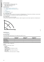
The ramps determine how quickly the product can accelerate and decelerate during start and stop or setpoint changes.
You can make the following settings:

acceleration time, 0.1 to 300 s

deceleration time, 0.1 to 300 s.

The times apply to the acceleration from 0 rpm to a fixed maximum speed and the deceleration from a fixed maximum speed to 0 rpm,
respectively.
At short deceleration times, the deceleration of the product may depend on load and inertia as there is no possibility of actively braking the
product.
If the power supply is switched off, the deceleration of the product only depends on the load and inertia.

X

Y

0

1

3

4

5

6

7

2

TM069798

Pos.

Description

Y

Speed

X

Time

1

Fixed maximum

2

User-set maximum

3

User-set minimum

4

Fixed initial ramp

5

Fixed final ramp

6

Ramp time up

7

Ramp time down

6.19 "Direction of rotation"

Use this function to select the desired direction of motor rotation when looking at the motor shaft end from the drive side.

clockwise

counterclockwise

The displayed direction of rotation applies when the digital inputs for reversing the rotation are not active.

6.20 "Skip band"

Use this function to select a skip band within the range from user-set minimum speed to user-set maximum speed, if continuous operation is
not required. The upper and lower speeds are stated in percentage of rated speed.
The purpose of the skip band is to avoid certain speeds which may cause noise or vibrations. If no skip band is required, select "-".

Related information

6.13 "Operating range"

6.21 "Standstill heating"

Use this function to avoid condensation in humid environments. 
When you set the function to 

Active

 and the product is in operating mode 

Stop

, a low AC voltage is applied to the motor windings. The

voltage is not high enough to make the motor rotate, but ensures that sufficient heat is generated to avoid condensation in the product,
including the electronic parts in the drive.

Remember to remove the drain plugs and fit a cover over the product.

Related information

4.1.4 Installing the product outdoors or in areas with high humidity

6.22 "Alarm handling"

This setting determines how the pump must react in case of a sensor failure. 
Alarm or warning types:

Warning

53

English (GB)

Summary of Contents for RADIOMODULE 2G4

Page 1: ...MGE motors Installation and operating instructions MGE motors Installation and operating instructions Other languages http net grundfos com qr i 98246988 GRUNDFOS INSTRUCTIONS ...

Page 2: ......

Page 3: ...og driftsinstruktion 144 Español ES Instrucciones de instalación y funcionamiento 214 Français FR Notice d installation et de fonctionnement 285 Nederlands NL Installatie en bedieningsinstructies 356 Polski PL Instrukcja montażu i eksploatacji 427 Svenska SE Monterings och driftsinstruktion 498 Appendix A 567 3 Table of contents ...

Page 4: ... speed 39 6 5 Control mode 40 6 6 Analog inputs 40 6 7 Pt100 1000 inputs 42 6 8 Digital inputs 43 6 9 Digital inputs outputs 44 6 10 Signal relay Relay outputs 45 6 11 Analog output 46 6 12 Controller Controller settings 47 6 13 Operating range 47 6 14 External setpoint function 48 6 15 Predefined setpoints 50 6 16 Limit exceeded function 51 6 17 Stop at min speed 52 6 18 Ramps 53 6 19 Direction o...

Page 5: ... a hazardous situation which if not avoided will result in death or serious personal injury WARNING Indicates a hazardous situation which if not avoided could result in death or serious personal injury CAUTION Indicates a hazardous situation which if not avoided could result in minor or moderate personal injury The hazard statements are structured in the following way SIGNAL WORD Description of th...

Page 6: ...or an open loop system in which the setpoint signal is used as a speed control signal The motors incorporate an operating panel which is available in various versions Detailed motor settings are made with Grundfos GO Remote Furthermore you can read important operating parameters via Grundfos GO Remote The motors incorporate a functional module The functional module is available in various versions...

Page 7: ...P N U in I 1 1 f in H p H z P2 I SF Amp rpm Xxxxxxxxxxx E P Motor DK 8850 Bjerringbro Denmark A TM064924 The position numbers refer to the table Env Type IP CL PF PB FM HMI Eff n max CIM Wgt DE kg NDE Tamb C A V P C Made in Hungary OUTPUT VARIANT INPUT Type P N Uin I 1 1 f in kW Hz P2 rpm o DK 8850 Bjerringbro Denmark V 1 2 3 4 5 6 7 8 9 10 11 12 13 14 15 16 17 18 19 20 21 22 23 24 25 26 27 TM0702...

Page 8: ...ion Type of motor unit Complete motor unit with terminal box B Basic motor unit without terminal box K Kit for basic motor unit without terminal box MG Motor Grundfos E Electronic control 71 Frame size according to IEC centre line height of the motor shaft in mm foot mounted motor 80 90 100 112 132 160 Size of foot Not defined for frame sizes 71 and 80 S Small M Medium L Large A1 Length of stator ...

Page 9: ... 80 5 5 H2 105 7 5 11 11 1 Frame size 71 80 90 2 Frame size 100 112 132 160 3 Only for 3 x 200 230 VAC 2 7 Identification of the functional module You can identify the fitted module in one of the following ways Grundfos GO Remote You can identify the functional module in the Fitted modules menu under Status Motor display For motors fitted with the advanced operating panel you can identify the func...

Page 10: ...d einHunga ry OU TPUT VARIANT INPU T TEFC Typ e P N U in I 1 1 f in Hp Hz P2 I SF Amp rpm Xxxxxxxxxxx E P Motor DK 8850 Bjerringbro Denmark PB FM HMI CIM VARIANT Hp rpm TM064013 Operating panel variants Variant Designation HMI 100 Basic operating panel HMI 101 Basic operating panel for motors without a radio module HMI 200 Standard operating panel HMI 201 Standard operating panel for motors withou...

Page 11: ...ipment 4 1 1 Handling the product Observe local regulations concerning limits for manual lifting or handling The weight of the product is stated on the nameplate CAUTION Back injury Minor or moderate personal injury Use lifting equipment CAUTION Crushing of feet Minor or moderate personal injury Wear safety shoes Attach lifting equipment to the motor eyebolts Do not lift the product by the termina...

Page 12: ... drain holes in the product Connect the product permanently to the mains supply and activate the built in standstill heating function Related information 2 5 Drain holes 4 1 3 Cooling the motor 6 21 Standstill heating 4 1 5 Installing the product in moist surroundings If you install the motor in moist surroundings or areas with high humidity ensure that the bottom drain hole is open As a result th...

Page 13: ...er 180 Do not twist the cable more than 90 180 TM055354 5 Position the plastic cover correctly over the four rubber pins C Make sure that the locking tabs A are placed correctly A A C TM055355 6 Fit the terminal box cover and make sure that it is turned 180 so that the buttons on the operating panel are aligned with the buttons on the plastic cover 13 English GB ...

Page 14: ...NG Electric shock Death or serious personal injury Connect the product to protective earth and provide protection against indirect contact in accordance with local regulations Protective earth conductors must have a yellow and green PE or yellow green and blue PEN colour marking 4 2 2 Protection against mains voltage transients The product is protected against mains voltage transients in accordanc...

Page 15: ...lled out of the cable entry Check that the supply voltage and frequency correspond to the values stated on the nameplate If you want to supply the product through an IT network make sure that you have a suitable product variant If you are in doubt contact Grundfos Mains connection on a single phase motor PE TM053494 Pos Description PE Protective earth L Phase N Neutral 4 2 5 2 Three phase connecti...

Page 16: ...DANGER Electric shock Death or serious personal injury If national legislation requires a Residual Current Device RCD or equivalent in the electrical installation this must be type B or better due to the nature of the constant DC leakage current The residual current circuit breaker must be marked TM066230 Take into account the total leakage current of all the electrical equipment in the installati...

Page 17: ... product is not damaged The product requires no additional protection 4 2 6 3 Overtemperature protection The electronic unit has a built in temperature sensor as an additional protection The product reduces the speed automatically if the temperature exceeds a certain level and it stops completely if the temperature keeps rising The product remains stopped for a set period After this period the pro...

Page 18: ...tentiometer or sensor 6 GND Protective earth A GENIbus A GENIbus A Y GENIbus Y GENIbus Y GND B GENIbus B GENIbus B Related information 4 2 4 Connecting an external switch 4 2 7 2 Standard functional module FM 200 Inputs and outputs The module has these connections two analog inputs two digital inputs or one digital input and one open collector output Grundfos Digital Sensor input and output two si...

Page 19: ...V C1 Common NO Normally open contact NC Normally closed contact Signal relay 2 PELV only C2 Common NO Normally open contact 10 DI3 OC1 Digital input output configurable Open collector Maximum 24 V resistive or inductive 4 AI1 Analog input 0 20 mA or 4 20 mA 0 5 3 5 V 0 5 V or 0 10 V 2 DI1 Digital input configurable Digital input 1 is factory set to be start or stop input where an open circuit resu...

Page 20: ... from other circuits All control terminals are supplied with protective extra low voltage PELV ensuring protection against electric shock Signal relay 1 LIVE You can connect supply voltages up to 250 VAC to the output PELV The output is galvanically separated from other circuits Therefore you can connect the supply voltage or protective extra low voltage to the output as desired Signal relay 2 PEL...

Page 21: ...open contact 18 GND Protective earth 11 DI4 OC2 Digital input output configurable Open collector Maximum 24 V resistive or inductive 19 Pt100 1000 input 2 Pt100 1000 sensor input 17 Pt100 1000 input 1 Pt100 1000 sensor input 12 AO Analog output 0 20 mA or 4 20 mA 0 10 V 9 GND Protective earth 14 AI3 Analog input 0 20 mA or 4 20 mA 0 5 3 5 V 0 5 V or 0 10 V 1 DI2 Digital input configurable 21 LiqTe...

Page 22: ...put 24 GDS RX Grundfos Digital Sensor input 7 AI2 Analog input 0 20 mA or 4 20 mA 0 5 3 5 V 0 5 V or 0 10 V Related information 4 2 4 Connecting an external switch 4 2 8 Signal relays The motor has two outputs for potential free signals via two internal relays You can set the signal outputs to Operation Pump running Ready Alarm and Warning The functions of the two signal relays appear from the tab...

Page 23: ... C NC NO C NC NO C NC NO NC NO C C NC NO Normal Min or Max Grundfos Eye is rotating yellow Warning but the pump or motor is running Operation Pump running Ready Alarm Warning Operating mode C NC NO C NC NO NC NO C NC NO C C NC NO Manual Grundfos Eye is permanently yellow Warning but the pump or motor was stopped via a Stop command Operation Pump running Ready Alarm Warning Operating mode NC NO C N...

Page 24: ...necting signal cables 4 2 9 1 Connecting signal cables 1 Connect the screens of the cables to the frame at both ends with good connection The screens must be as close as possible to the terminals TM021325 2 Connect the signal cables to the terminals 3 Tighten the terminal screws Related information 4 2 9 Signal cables 4 2 10 Bus connection cable 4 2 10 1 Connecting a 3 core bus cable For the bus c...

Page 25: ...ignal the local settings made via Grundfos GO Remote or the advanced operating panel will be overruled In case the bus signal fails the product will run with the local settings made via Grundfos GO Remote or the advanced operating panel 4 2 11 Installing a communication interface module DANGER Electric shock Death or serious personal injury Switch off the power supply to the product including the ...

Page 26: ... 4 Fit the module by aligning it with the three plastic holders F and the connection plug G Press the module home using your fingers F G TM069907 5 Fit and tighten the screw E to 1 3 Nm 6 Make the electrical connections to the module as described in the instructions supplied with the module 7 Connect the cable screens of the bus cables to protective earth via one of the earth clamps H H TM069908 2...

Page 27: ... module through one of the cable glands TM064085 Fig MGE 71 80 90 TM070190 Fig MGE 100 112 132 160 9 Fit the CIM cover 10 If the module is supplied with an FCC label fix the label on the terminal box FCC TM069909 27 English GB ...

Page 28: ...r motors without a radio module HMI 300 Advanced operating panel HMI 301 Advanced operating panel for motors without a radio module Grundfos GO Remote All settings are saved if the power supply is switched off 5 1 1 Basic operating panel Pos Symbol Description 1 Grundfos Eye The indicator light shows the operating status of the product 2 Radio communication The button enables radio communication w...

Page 29: ...y of settings 5 1 2 1 Setting the setpoint in constant parameter mode The following applies for motors set to operate in Const other val Set the desired setpoint by pressing the Up or Down buttons The green light fields on the operating panel indicate the setpoint set The following example applies to a pump or motor in an application where a pressure sensor gives a feedback to the pump or motor Th...

Page 30: ...tor was stopped by pressing the Start Stop button Start the motor by pressing the Start Stop button If the motor was stopped by pressing and holding the Down button Start the motor by pressing and holding the Up button 5 1 2 6 Stopping the motor Stop the motor in one of the following ways Press the Start Stop button Press and hold the Down button until all light fields are off Use Grundfos GO Remo...

Page 31: ...ows save changed values reset alarms and expand the value field enable radio communication with Grundfos GO Remote and other products of the same type When you try to establish radio communication between the product and Grundfos GO Remote or another product the green indicator light in Grundfos Eye flashes In the controller display a note states that a wireless device wants to connect to the prod...

Page 32: ...ts of the same type and size 7 Setpoint 5 00 bar Operaring mode Normal Actual controlled value 4 90 bar Control mode Const pressure Status Settings Assist 1 2 3 5 6 7 8 9 Slave The icon indicates that the product is functioning as a slave in a system with products of the same type and size 8 Setpoint 5 00 bar Operaring mode Normal Actual controlled value 4 90 bar Control mode Const pressure Status...

Page 33: ...mp system Pump 2 multi pump system Pump 3 multi pump system Pump 4 multi pump system Only available if an advanced functional module type FM 300 is fitted Settings MGE Multimotor system Setpoint Operating mode Set manual speed Set user defined speed Control mode Analog inputs Analog input 1 setup Analog input 2 setup Analog input 3 setup Pt100 1000 inputs Pt100 1000 input 1 setup Pt100 1000 input ...

Page 34: ... disable radio comm General settings Language Set date and time Units Enable disable settings Delete history Define Home display Display settings Store actual settings Recall stored settings Run start up guide Only available if an advanced functional module type FM 300 is fitted Assist MGE Multimotor system Assisted pump setup Setup analog input Setting of date and time Setup of multi pump system ...

Page 35: ...e Home button to reject connection Symbol Description Press OK on the operating panel to connect the product with Grundfos GO Remote Setpoint 5 00 bar Operaring mode Normal Actual controlled value 4 90 bar Control mode Const pressure Status Settings Assist 1 2 3 5 6 7 8 9 Press the Home button to reject connection You can choose between these communication types radio communication infrared commun...

Page 36: ...ulting system setpoint Actual controlled value Motor speed Power consumption Power consumption system Energy consumption Energy consumption system Acc flow specific energy Operating hours Motor current Number of starts Operating hours system Pt100 1000 input 1 Pt100 1000 input 2 Analog Output Analog input 1 Analog input 2 Analog input 3 Digital input 1 Digital input 2 Digital input output 3 Digita...

Page 37: ...fined setpoint Analog output External setpoint funct Signal relay 1 Signal relay 2 Limit 1 exceeded Limit 2 exceeded Alternating operation time Sensor to be used Time for pump changeover Standstill heating Alarm handling Motor bearing monitoring Direction of rotation Service Date and time Store settings Recall settings Undo Pump name Connection code Unit configuration Only available if an advanced...

Page 38: ...re rotating The power is on The motor is running The indicator lights are rotating in the direction of rotation of the motor when seen from the non drive end Two opposite green indicator lights are permanently on The power is on The motor is not running One yellow indicator light is rotating Warning The motor is running The indicator light is rotating in the direction of rotation of the motor when...

Page 39: ...view for the advanced operating panel 5 2 2 Menu overview for Grundfos GO Remote 6 1 Setpoint When you have selected the desired control mode set the setpoint Related information 6 5 Control mode 6 2 Operating mode Possible operating modes Normal The product runs according to the selected control mode Stop The product stops Min The product runs at minimum speed Max The product runs at maximum spee...

Page 40: ... Use this control mode to control the motor speed You can set the desired speed in percentage of the maximum speed in the range from user set minimum speed to user set maximum speed H Q TM057957 Related information 6 13 Operating range 6 6 Analog inputs The inputs and outputs available depend on the functional module fitted in the motor Functional module Analog input 1 Terminal 4 Analog input 2 Te...

Page 41: ...harge press 3 Diff press outlet 4 Diff press pump 5 Press 1 external 6 Press 2 external 7 Diff press ext 8 Storage tank level 9 Feed tank level 10 Pump flow 11 Flow external 12 Liquid temp 13 Temperature 1 14 Temperature 2 15 Differential temp 16 Ambient temp Not shown Other parameter Not shown Unit Parameter Available units Pressure bar m kPa psi ft Level m ft in Pump flow m3 h l s yd3 h gpm Liqu...

Page 42: ...the Con diff press Con diff temp or Const flow rate control modes you must configure both sensors as Feedback sensor Related information 6 6 Analog inputs 6 7 Pt100 1000 inputs The inputs and outputs available depend on the functional module fitted in the motor Functional module Pt100 1000 input 1 Terminals 17 18 Pt100 1000 input 2 Terminals 18 19 FM 100 basic FM 200 standard FM 300 advanced In or...

Page 43: ...indication if any is reset Dry running When this function is selected lack of inlet pressure or water shortage dry running can be detected When this happens the pump stops The pump cannot restart as long as the input is activated This requires the use of an accessory such as these a pressure switch installed on the inlet side of the pump a float switch installed on the inlet side of the pump Accum...

Page 44: ...ut interrupt Active with after run The duration time T2 is the time which together with the mode determines how long the selected function is active Range 0 15 000 seconds T3 T3 T1 T2 T3 T1 T2 T1 T2 T1 T2 T1 T1 T2 T2 T1 T1 T3 T2 1 2 3 4 TM070000 Pos Description 1 Digital input 2 Active with interrupt 3 Active without interrupt 4 Active with after run T1 Activation delay T2 Duration time T3 The per...

Page 45: ...put Not active Ext stop Min Max User defined speed External fault Alarm resetting Dry running Accumulated flow Reverse rotation Predefined setpoint 2 digital input output 3 Predefined setpoint 3 digital input output 4 Local motor stop Activate output Functions if the digital input or output is set to output Not active Ready Alarm Operation Pump running Warning Limit 1 exceeded Limit 2 exceeded Dig...

Page 46: ... temperature of the motor electronics reaches a preset limit value In this way the relay activates external cooling to add additional cooling to the motor Digital input 1 state Follow digital input 1 If digital input 1 is triggered digital output is also triggered Digital input 2 state Follow digital input 2 If digital input 2 is triggered digital output is also triggered Digital input 3 state Fol...

Page 47: ...are preset from the factory However if the factory setting is not the optimum setting you can change the gain and integral time 1 Set the gain Kp within the range from 0 1 to 20 2 Set the integral time Ti within the range from 0 to 3600 seconds If you select 0 seconds the controller functions as a P controller You can set the controller to inverse control This means that if you increase the setpoi...

Page 48: ...e setpoint by an external signal via one of the analog inputs If the advanced functional module type FM 300 is fitted you can also influence the setpoint via one of the Pt100 1000 inputs To enable the function set one of the analog inputs or Pt100 1000 inputs to Setpoint influence with Grundfos GO Remote or to Ext setpoint infl with the advanced operating panel Example of setpoint influence in con...

Page 49: ...oint of 60 the actual setpoint is 0 60 x 85 25 25 61 100 0 100 0 3 5 V 0 5 5 V 0 10 V 0 20 mA 0 20 mA 204 C 4 50 25 61 85 Y1 Y2 Y3 Y4 X1 Y X TM070253 Pos Description X External input signal from 0 to 100 Y Setpoint influence from 0 to 100 X1 Actual input signal 60 Y1 Y1 Fixed maximum speed in percentage Y2 Y2 Setpoint speed in percentage Y3 Y3 Actual setpoint speed in percentage Y4 Y4 User set min...

Page 50: ... is a straight line between the points and a horizontal line before the first point and after the last point 100 0 3 5 V 0 5 5 V 0 10 V 0 20 mA 0 20 mA 204 C 4 50 X 100 0 Y TM070254 Pos Description X External input signal from 0 to 100 Y Setpoint influence from 0 to 100 6 15 Predefined setpoints You can set and activate seven predefined setpoints by combining the input signals to digital inputs 2 ...

Page 51: ...itor a measured parameter or one of the internal values such as speed motor load or motor current If a set limit is reached a selected action can take place You can set two limit exceeded functions meaning that you can monitor two parameters or two limits of the same parameter simultaneously The function requires setting of the following parameters Measured Set the measured parameter to be monitor...

Page 52: ...ore than 8 seconds reset the limit exceeded warning 1 2 4 4 5 6 3 A Y X TM070085 X Time in seconds Y Pressure in bar Pos Parameter Setting 1 Measured Discharge pressure 2 Limit 5 bar 3 Hysteresis band 2 bar 4 Limit exceeded when below limit 5 Detection delay 5 seconds 6 Resetting delay 8 seconds A Limit exceeded function active Action Warning 6 17 Stop at min speed This stop function can be utilis...

Page 53: ...ayed direction of rotation applies when the digital inputs for reversing the rotation are not active 6 20 Skip band Use this function to select a skip band within the range from user set minimum speed to user set maximum speed if continuous operation is not required The upper and lower speeds are stated in percentage of rated speed The purpose of the skip band is to avoid certain speeds which may ...

Page 54: ...ate the replacement time 6 24 Service 6 24 1 Time to next service Motor bearing service This display shows when to replace the motor bearings The controller monitors the operating pattern of the motor and calculates the period between bearing replacements Displayable values in 2 years in 1 year in 6 months in 3 months in 1 month in 1 week Now 6 24 2 Bearing replacements The display shows the numbe...

Page 55: ...ultaneously for at least 5 seconds Related information 5 1 2 Standard operating panel 5 1 3 Advanced operating panel 6 31 Delete history The function is only available in the advanced operating panel Use this function to delete the following historical data Delete operating log Delete energy consumption 6 32 Define Home display The function is only available in the advanced operating panel Set the...

Page 56: ...sks you to press OK or theRadio communication button on the product the product has no connection code or has a different connection code In this case press OK or the Radio communication button to establish connection 6 39 Run start up guide The function is only available in the advanced operating panel The startup guide automatically starts when you start the product for the first time You can al...

Page 57: ...e main purpose of the function is to ensure an even amount of running hours and to ensure that the other pump or motor starts if the duty pump or motor stops due to an alarm You can choose between two alternating operating modes Alternating operation time The change from one pump or motor to the other is based on time Alternating operation energy The change from one pump or motor to the other is b...

Page 58: ...Set the needed analog and digital inputs via Grundfos GO Remote according to the connected equipment and the required functionality See Assisted pump setup 8 Assign a name to the motor using Grundfos GO Remote See Pump name Motor name 9 Select the Assist menu and Setup of multi pump system 10 Select the desired multimotor function See Multipump or multimotor function 11 Press the Right button to c...

Page 59: ...pment and the required functionality See Assisted pump setup 3 Select the Assist menu on one of the motors and Setup of multi pump system setup of multimotor system 4 Press the Right button to continue 5 Select Wireless as the communication method to be used between the two motors 6 Press the Right button to continue 7 Select the desired multimotor function See Multipump or multimotor function 8 P...

Page 60: ...ltipump or multimotor system with the advanced operating panel 1 Go to Assist 2 Select Setup of multi pump system 3 Press the Right button to continue 4 Press OK to confirm No multi pump function 5 Press the Right button to continue 6 Press OK to confirm 6 47 Description of control mode The function is only available in the advanced operating panel The function describes each of the control modes ...

Page 61: ...Normal Normal Set user defined speed 67 67 Control mode Constant curve Constant curve Buttons on product Active Active Controller Kp 0 5 Ti 0 5 Kp 0 5 Ti 0 5 Operating range 25 100 16 100 Ramps Ramp up time 1 s Ramp down time 3 s Ramp up time 10 s Ramp down time 10 s Number 1 1 Radio communication Activated Activated Analog input 1 Not active Function Setpoint influence Measured parameter Other Si...

Page 62: ...itch off the power supply to the product and to the signal relays Check that the terminal box cover is intact before spraying water on the product To clean the motor follow the procedure below 1 Let the motor cool down first to avoid condensation 2 Spray it with cold water 8 Technical data 8 1 Technical data single phase motors DANGER Electric shock Death or serious personal injury Use the recomme...

Page 63: ...x 200 240 V 10 10 50 60 Hz PE Motor size kW Minimum A Maximum A 1 1 10 20 1 5 10 20 2 2 13 35 3 16 35 4 25 35 5 5 32 35 You can use standard as well as quick blow or slow blow fuses Related information 4 2 6 1 Overvoltage and undervoltage protection 8 2 1 Leakage current AC The leakage currents are measured without any load on the shaft and in accordance with EN 61800 5 1 2007 3 x 380 500 V 10 10 ...

Page 64: ...16 AWG Maximum cable length 500 m Open collector digital outputs OC Current sinking capability 75 mADC no current sourcing Load types Resistive and or inductive Low state output voltage at 75 mADC Maximum 1 2 VDC Low state output voltage at 10 mADC Maximum 0 6 VDC Overcurrent protection Yes Screened cable 0 5 1 5 mm2 28 16 AWG Maximum cable length 500 m Analog inputs AI Voltage signal ranges 0 5 3...

Page 65: ...ong wires LiqTec sensor inputs Use a Grundfos LiqTec sensor only Screened cable 0 5 1 5 mm2 28 16 AWG Grundfos Digital Sensor input and output GDS Use Grundfos Digital Sensor only Power supplies 5 V 24 V 5 V Output voltage 5 VDC 5 to 5 Maximum current 50 mADC sourcing only Overload protection Yes 24 V Output voltage 24 VDC 5 to 5 Maximum current 60 mADC sourcing only Overload protection Yes Digita...

Page 66: ...6 364 5 56 1 2900 4000 and 4000 5900 rpm Supply voltage Power kW L mm W mm H mm Weight kg 1 x 200 230 V 0 25 234 212 219 10 1 0 37 234 212 219 10 1 0 55 234 212 219 10 1 0 75 234 212 219 11 2 1 1 234 212 219 12 1 5 234 212 219 13 2 2900 4000 and 4000 5900 rpm Supply voltage Power kW L mm W mm H mm Weight kg 3 x 380 500 V 0 25 274 268 219 11 8 0 37 274 268 219 11 8 0 55 274 268 219 11 8 0 75 274 26...

Page 67: ... 214 212 219 9 4 0 75 214 212 219 10 2 1450 2000 2200 rpm Supply voltage Power kW L mm W mm H mm Weight kg 3 x 380 500 V 0 25 254 268 219 10 3 0 37 254 268 219 10 3 0 55 254 268 219 11 1 0 75 254 268 219 11 9 1 1 274 268 219 15 3 2 2 334 291 296 7 26 7 3 0 334 291 296 7 29 5 4 0 334 291 296 7 32 5 5 5 389 346 364 5 50 7 5 389 346 364 5 53 5 2900 4000 and 4000 5900 rpm Supply voltage Power kW L mm ...

Page 68: ...ted harmonics PWH requirements of EN 61000 3 12 If required by the distribution network operator compliance can be obtained in the following way The impedance of the mains cables between the motor and the point of common coupling PCC must be equivalent to the impedance of a 50 m cable with a cross section of 0 5 mm C3 fulfils the requirements for industrial areas Note When the motors are installed...

Page 69: ... 5 x M20 1 x M32 5 x M20 Related information 4 1 2 Cable entries 8 5 6 Torques for terminals Terminal Thread size Maximum torque Nm L1 L2 L3 L N M4 2 35 NC C1 C2 NO M2 5 0 5 1 26 A Y B M2 0 5 8 5 7 Sound pressure level Motor kW Rated maximum speed min 1 Speed min 1 Sound pressure level ISO 3743 dB A 1 x 200 240 V 3 x 200 240 V 3 x 380 500 V 0 25 0 75 2000 1500 37 37 2000 43 43 4000 3000 50 50 4000...

Page 70: ... 2000 1500 2000 2200 1500 48 2000 55 4000 3000 31 60 4000 68 69 5900 4000 64 5900 74 4 2000 1500 2000 2200 1500 48 2000 55 4000 3000 61 61 4000 68 69 5900 4000 64 5900 74 5 5 2000 1500 2000 2200 1500 58 2000 61 4000 3000 64 61 4000 72 69 5900 4000 64 5900 74 7 5 2000 1500 2000 2200 1500 58 2000 61 4000 3000 66 4000 73 5900 4000 69 5900 79 11 4000 3000 66 4000 73 5900 4000 69 5900 79 70 English GB ...

Page 71: ...res reduces the expected product life If the motor operates at ambient temperatures between 50 and 60 C select an oversized motor Contact Grundfos for further information 8 6 3 Installation altitude The installation altitude is the height above sea level of the installation site Products installed up to 1000 m above sea level can be loaded 100 The motors can be installed up to 3500 m above sea lev...

Page 72: ...undings 8 6 5 Turbine operation To increase the life of the product do not operate the product at a higher speed than the maximum speed stated on the nameplate 9 Disposing of the product WARNING Magnetic field Death or serious personal injury Persons with pacemakers dismantling this product must exercise caution when handling the magnetic materials embedded in the rotor This product or parts of it...

Page 73: ...14 2014 applies to Canada only UL 1004 1 2015 applies to USA only Pour le Canada Codes de l électricité Ce produit est conforme au code canadien de l électricité et au code national de l électricité américain Ce produit a été testé selon les normes nationales s appliquant aux moteurs protégés électroniquement CSA 22 2 100 04 2009 s applique au Canada uniquement UL 1004 1 Juin 2011 s applique aux É...

Page 74: ...r and the drive which reduces the life of the product Short circuit current If a short circuit occurs the pump can be used on a mains supply delivering not more than 5000 RMS symmetrical amperes 600 V maximum Fuses Fuses used for motor protection must be rated for minimum 500 V Motors up to and including 10 hp require class K5 UL listed fuses Any UL listed fuse can be used for motors of 15 hp Bran...

Page 75: ...6th Floor Aju Building 679 5 Yeoksam dong Kangnam ku 135 916 Seoul Korea Tel 82 2 5317 600 Fax 82 2 5633 725 Latvia SIA GRUNDFOS Pumps Latvia Deglava biznesa centrs Augusta Deglava ielā 60 LV 1035 Rīga Tel 371 714 9640 7 149 641 Fax 371 914 9646 Lithuania GRUNDFOS Pumps UAB Smolensko g 6 LT 03201 Vilnius Tel 370 52 395 430 Fax 370 52 395 431 Malaysia GRUNDFOS Pumps Sdn Bhd 7 Jalan Peguam U1 25 Gle...

Page 76: ...emarks displayed in this material including but not limited to Grundfos the Grundfos logo and be think innovate are registered trademarks owned by The Grundfos Group All rights reserved 2019 Grundfos Holding A S all rights reserved ...

Reviews: