


Pos.
Description
X:
External input signal from 0 to 100 %
Y:
Setpoint influence from 0 to 100 %
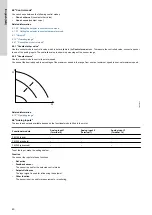
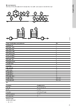
6.14.1.2 "Linear with stop"
In the input signal range from 20 to 100 %, the setpoint is influenced linearly. If the input signal is below 10 %, the motor changes to
the
Stop
operating mode. If the input signal increases more than 15 %, the operating mode changes back to
Normal
.
100
3.5 V
5 V
10 V
20 mA
20 mA
0, B
20
15
10
0
0.5
0
0
0
4
-50
204°C
Y
X
A
TM070542
Pos.
Description
X:
External input signal from 0 to 100 %
Y:
Setpoint influence from 0 to 100 %
A:
Normal
B:
Stop
6.14.1.3 "Influence table"
The setpoint is influenced by a curve made of two to eight points. There is a straight line between the points and a horizontal line before the
first point and after the last point.
100 %
0
3.5 V
0.5
5 V
0
10 V
0
20 mA
0
20 mA
204 °C
4
-50
X
100
0
Y
TM070254
Pos.
Description
X:
External input signal from 0 to 100 %
Y:
Setpoint influence from 0 to 100 %
6.15 "Predefined setpoints"
You can set and activate seven predefined setpoints by combining the input signals to digital inputs 2, 3 and 4 as shown in the table below. Set
the digital inputs 2, 3 and 4 to
Predefined setpoints
if all seven predefined setpoints are to be used. You can also set one or two of the digital
inputs to
Predefined setpoints
which, however, limits the number of predefined setpoints available.
Digital inputs
Setpoint
2
3
4
0
0
0
Normal setpoint or
Stop
1
0
0
Predefined setpoint 1
0
1
0
Predefined setpoint 2
1
1
0
Predefined setpoint 3
50
English (GB)
Summary of Contents for RADIOMODULE 2G4
Page 2: ......