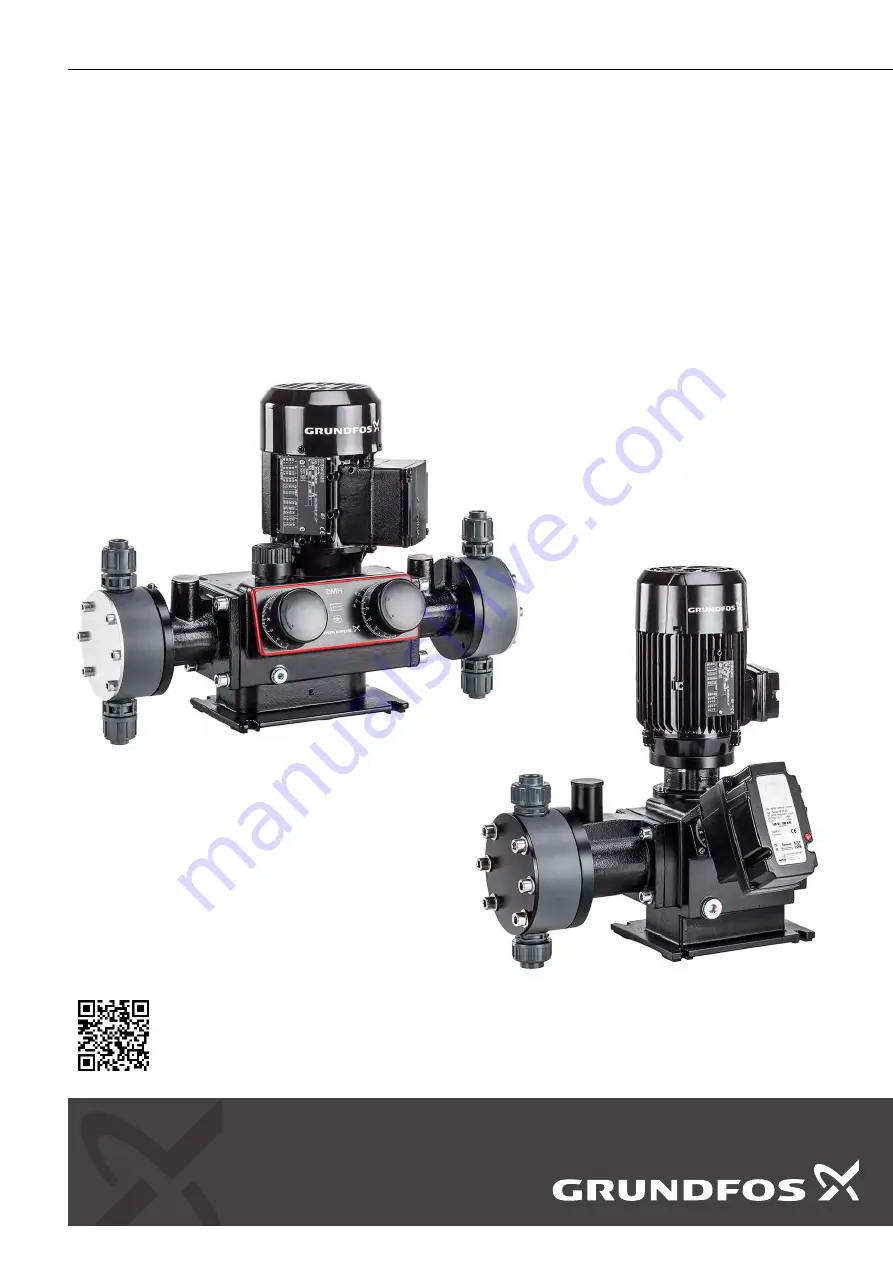
DMH 25X
Dosing pump
Installation and operating instructions
DMH 25x
http://net.grundfos.com/qr/i/99558949
GRUNDFOS
INSTRUCTIONS
Page 1: ...DMH 25X Dosing pump Installation and operating instructions DMH 25x Installation and operating instructions http net grundfos com qr i 99558949 GRUNDFOS INSTRUCTIONS ...
Page 2: ......
Page 3: ...U Telepítési és üzemeltetési utasítás 285 Italiano IT Istruzioni di installazione e funzionamento 325 Nederlands NL Installatie en bedieningsinstructies 365 Polski PL Instrukcja montażu i eksploatacji 405 Português PT Instruções de instalação e funcionamento 445 Română RO Instrucţiuni de instalare şi utilizare 485 Srpski RS Uputstvo za instalaciju i rad 525 Svenska SE Monterings och driftsinstrukt...
Page 4: ...the pump 33 8 7 Shutdown 33 9 Operation 34 9 1 Switching on off 34 9 2 Setting the dosing capacity 34 9 3 Using the AR control unit optional 34 9 4 Electric servomotor optional 34 9 5 Electronic preselection counter optional 34 9 6 Electrically heated dosing head optional 34 10 Maintenance 35 10 1 General notes 35 10 2 Diaphragm leakage control for diaphragm leakage detection 35 10 3 Cleaning and ...
Page 5: ...substances 2 4 Safety conscious working The safety instructions in this manual applicable national health and safety regulations and any operator internal working operating and safety regulations must be observed 2 5 Safety instructions for the operator user Hazardous hot or cold parts on the pump must be protected to prevent accidental contact Leakages of dangerous substances e g hot toxic must b...
Page 6: ... in ac cordance with the EC directive 2014 34 EU refer to the enclosed manual ATEX approved pumps in addition to this manual If the assumption is made that a safe operation is no longer possible switch off the pump and protect it against unintentional operation This action should be taken if the pump has been damaged if the pump no longer seems to be operational if the pump has been stored for an ...
Page 7: ... DN 32 T PTFE SS Stainless steel 1 4401 EN 10027 2 316 AISI C Ceramic up to DN 20 Y Alloy C 4 2 4610 EN 10027 2 Terminal box position also AR control or VFD position DMH1150 10D B PVC V G X E1B8B8XEMAG X Opposite side of dosing head 3 o clock D Towards dosing head 9 o clock S Towards adjusting knob 6 o clock R Opposite side of adjusting knob 12 o clock Supply voltage DMH1150 10D B PVC V G X E1B8B8...
Page 8: ...AG EM Standard motor without certificates E0 Motor with PTC for thermal protection without certificates E1 EX motor type EX II 2G EEx e II T3 without certificates E2 EX motor type EX II 2GD EEx de IIC T4 without PTC without certificates E3 Pump with API approval without pump and motor certifi cates E5 EX motor type EX II 2GD EEx de IIC T4 with PTC without certificates FA VFD variable frequency dri...
Page 9: ... l h bar n min l h bar n min DMH 251 DMH 2 2 25 2 2 25 14 2 6 25 17 4 4 25 29 DMH 2 3 16 2 3 16 14 2 8 16 17 4 5 16 29 DMH 2 4 10 2 4 10 14 2 9 10 17 5 10 29 DMH 4 5 25 4 5 25 29 5 4 25 35 9 25 58 DMH 4 9 16 4 9 16 29 5 9 16 35 9 8 16 58 DMH 5 10 5 10 29 6 10 35 10 10 58 DMH 11 25 11 25 63 13 25 75 22 25 126 DMH 12 16 12 16 63 14 16 75 24 16 126 DMH 13 10 13 10 63 16 10 75 25 10 126 DMH 17 25 17 2...
Page 10: ...680 16 146 DMH 750 4 750 4 73 900 4 88 1500 4 146 DMH 770 10 770 10 98 924 10 118 DMH 880 10 880 10 112 1056 10 134 DMH 1150 10 1150 10 146 DMH 1500 4 1500 4 146 1 Dosing capacity per dosing head double the capacity for double head pumps 2 Maximum counterpressure Note The pump can be operated in the range between 10 and 100 of the maximum dosing capacity 3 3 2 Accuracy Dosing flow fluctuation smal...
Page 11: ... DMH 257 75 5 1 Testing according to DIN 45635 01 KL3 3 5 Electrical data 3 5 1 Enclosure class The enclosure class depends on the motor variant selected see motor nameplate The specified enclosure class can only be ensured if the power supply cable is connected with the same degree of protection Pumps with electronics The enclosure class is only met if the sockets are protected The data regarding...
Page 12: ...esistance and suitability of the pump for specific dosing media please contact Grundfos The dosing medium must have the following basic characteristics for the standard pumps liquid non abrasive The dosing of abrasive media is possible with certain versions on request non flammable The dosing of inflammable media is possible with certain versions of explosion proof pumps in accordance with ATEX Ma...
Page 13: ...tion missing or unsuitable packaging of the pump residual media or leaking oil Before returning the pump to Grundfos Water Treatment for service the safety declaration at the end of these instructions must be filled in by authorised personnel and attached to the pump in a visible position Caution If a pump has been used for a medium which is injurious to health or toxic the pump will be classified...
Page 14: ...d seals the stroke area from the drive area The hydraulic driven movement of the PTFE diaphragm Q displaces an equivalent volume of dosing medium from the dosing head 2 into the dosing line With the suction stroke the piston creates a low pressure which is established in the dosing head The ball valve 3b on the dosing side closes and the dosing medium flows through the suction valve 3a into the do...
Page 15: ...εχ 1p F L M 3b 3a 9p 3p 2p 5p 6p 2 Q 4p TM036450 DMH 254 1p F L M 3b 3a 9p 3p 2p 5p 4p 2 Q 6p TM036451 DMH 255 15 English GB ...
Page 16: ...ling screw with dipstick 5 1 1 Combined pressure relief and degassing valve The combined pressure relief and degassing valve M opens if there is an excessive pressure build up in the dosing system and provokes the constant degassing of the hydraulic medium 5 1 2 Diaphragm protection system AMS The diaphragm protection system AMS 9p has a keypad which is connected to the dosing diaphragm The dosing...
Page 17: ... the contact pressure gauge Functional principle of diaphragm leakage detection The non return valve and the gap between the diaphragms are factory filled with a separating agent paraffin oil They are set in such a way during start up on the test stand that there is always a hydraulically separated equilibrium between the valve and diaphragm gap the pressure gauge indicates 0 when the pump is runn...
Page 18: ... 9 179 152 84 16 124 180 117 5 5 4 DMH 254 436 492 156 20 252 G1 1 4 9 207 185 126 10 187 225 180 22 5 2 2 Dimensions of DMH 251 252 253 and 254 double head pumps D B B1 J C N A D1 E S1 S D2 C2 K F M K TM073718 All dimensions are in mm except for the thread designations Pump model A B C C1 D D1 D2 E F G J K M N S S1 DMH 251 432 336 97 5 14 192 G 5 8 9 160 152 85 5 16 116 180 117 5 5 9 DMH 252 432 ...
Page 19: ...9 234 185 126 10 253 225 180 10 5 5 2 4 Dimensions of DMH 255 single head pumps with flange on inlet side A E S1 K M F B1 B C J N D1 D D3 D4 D5 C2 D2 TM073712 All dimensions are in mm except for the thread designations Pump model Inlet flange D3 A B C C1 D D1 D2 D4 D5 E F G J K M N S1 DMH 255 DN32 510 492 156 20 254 G1 1 4 9 100 140 283 185 126 10 253 225 180 41 DMH 255 ANSI 1 1 4 510 492 156 20 2...
Page 20: ...9 234 185 126 10 253 225 180 10 5 5 2 6 Dimensions of DMH 255 double head pumps with flange on inlet side A K F M D1 E S1 K D B B1 D2 C2 D5 D4 D3 N C J TM073719 All dimensions are in mm except for the thread designations Pump model Inlet flange D3 A B C C1 D D1 D2 D4 D5 E F G J K M N S1 DMH 255 DN32 869 492 156 20 254 G1 1 4 9 100 140 283 260 126 10 253 300 180 41 DMH 255 ANSI 1 1 4 869 492 156 20...
Page 21: ...290 194 5 12 DMH 257 ANSI 1 1 4 589 572 170 24 5 278 9 89 140 280 241 128 5 25 262 290 194 5 5 2 8 Dimensions of DMH 257 double head pumps A D5 D4 E S1 K F M K C2 C N J B1 B D D1 D2 TM073720 All dimensions are in mm except for the thread designations Pump model Pump connec tion size D1 A B C C1 D D2 D4 D5 E F G J K M N S1 DMH 257 DN32 980 572 170 24 5 278 9 100 140 280 333 128 5 25 262 382 194 5 1...
Page 22: ...nstructions when handling chemicals Make sure that the pump is suitable for the actual dosing medium Caution The resistance of the parts that come into contact with the media depends on the media media temperature and op erating pressure Ensure that parts in contact with the me dia are chemically resistant to the dosing medium under operating conditions Note Further information on resistance with ...
Page 23: ...Ambient and operating conditions 6 2 3 Mounting surface The pump must be mounted on a flat surface 6 3 Mounting Mount the pump on a console or pump foundation using four screws Note The flow must run in the opposite direction to gravity 6 4 Approximate values when using pulsation dampers Caution Risk of damage to the system It is always recommended to use pulsation dampers for large high speed pum...
Page 24: ... 20 1 DMH 255 DMH 194 10 DN 20 5 DMH 270 10 DN 20 3 DMH 332 10 DN 20 1 5 DMH 403 10 DN 20 1 DMH 550 10 DN 20 1 5 DMH 257 DMH 272 16 DN 32 4 5 DMH 340 16 DN 32 3 DMH 440 10 DN 32 4 5 DMH 450 16 DN 32 1 5 DMH 520 16 DN 32 1 DMH 575 10 DN 32 3 DMH 680 16 DN 32 0 5 DMH 750 4 DN 32 1 5 DMH 770 10 DN 32 1 5 DMH 880 10 DN 32 1 DMH 1150 10 DN 32 0 5 DMH 1500 4 DN 32 0 5 24 English GB ...
Page 25: ...036296 Example of optimum installation Pos Components 1i Dosing tank 2i Electric agitator 3i Extraction device 4i Suction pulsation damper 5i Dosing pump 6i Relief valve 7i Pressure loading valve 8i Pulsation damper 9i Measuring glass 10i Injection unit 25 English GB ...
Page 26: ...e pump suction valve Note Observe section Approximate values when using pulsa tion dampers and if necessary request a system specific calculation from our calculation program 4i TM036300 Installation with suction side pulsation damper Note for discharge side installation Depending on the dosing flow and the line length it may be necessary to install a properly sized pulsation damper 4i on the disc...
Page 27: ...n If necessary use swept bends instead of elbows Observe the chemical manufacturer s safety instructions when handling chemicals Make sure that the pump is suitable for the actual dosing medium The flow must run in the opposite direction to gravity Caution The resistance of the parts that come into contact with the media depends on the media media temperature and op erating pressure Ensure that pa...
Page 28: ...ble for the electricity supply on which it will be used Warning Electrical connections must only be carried out by quali fied personnel Disconnect the power supply before connecting the power supply cable and the relay contacts Observe the local safety regulations The pump housing must only be opened by personnel au thorised by Grundfos Protect the cable connections and plugs against corrosion and...
Page 29: ...wer supply cable or plug Caution The assignment between the plug and socket connection and the pump must be labelled clearly e g by labelling the socket outlet Caution The pump can be automatically started by connecting the power supply Do not switch on the power supply until you are ready to start the pump 7 5 1 Versions with mains plug Insert the mains plug in the mains socket 7 5 2 Versions wit...
Page 30: ...ugh the oil filling opening F until the oil reaches the mark on the oil dipstick 3 Set the stroke length adjustment knob L to 0 8 1 3 Filling the dosing head for the initial start up for systems without flooded suction Warning When dosing dangerous media observe the correspond ing safety precautions Wear protective clothing gloves and goggles when work ing on the dosing head connections or lines A...
Page 31: ... Dosing head screws 2 Dosing head 3b Discharge valve F Oil filling screw with dipstick L Stroke length adjustment knob 1l Cover for stroke length adjustment knob M Pressure relief valve 1 Connect the electrical power supply 2 Depending on the installation start the pump where possible without counter pressure See installation example for easy deaeration of the dosing head in section Installation 3...
Page 32: ...emove the cover 1 m from the pressure relief valve 3 Start the pump 4 Using a screwdriver slowly turn the adjusting screw 2 m of the pressure relief valve counter clockwise until the desired opening pressure is obtained 2m 1m TM036465 Setting the pressure relief valve Caution Risk of damage to the pump or system When blocked the pressure relief valve does not work properly and can produce pressure...
Page 33: ...ating the pump see sections Operation and Maintenance if necessary section Fault finding chart Related information 9 1 Switching on off 10 1 General notes 11 Fault finding chart 8 7 Shutdown Warning Wear protective clothing gloves and goggles when work ing on the dosing head connections or lines Do not allow any chemicals to leak from the pump Collect and dispose of all chemicals correctly Note If...
Page 34: ... application tighten the locking screw 2l so that the stroke length adjustment knob can still be turned cannot be turned any more 5 Replace the cover 1l Caution The pump cannot be operated if the stroke length adjust ment knob is fully open Depending on the pump adjust ment this value may already be lower than 100 on the scale for system pressures higher than 100 bar Open the stroke length adjustm...
Page 35: ...tenance intervals Checking the oil level Check the oil level every two weeks and add oil if necessary Cleaning the valves At least every 12 months or after 4 000 operating hours If the pump does not perform In the event of a fault Clean the valves and replace if necessary for stainless steel valves inner valve parts Changing diaphragms and gear oil At least every 12 months or after 8 000 operating...
Page 36: ...70 Stainless steel 1 or plastic 2 DN 20 valve spring loaded as an option 2 1 TM036471 DN 32 valve suction side 1 and discharge side 2 Caution The O rings must be correctly placed in the specified groove Observe the flow direction indicated by an arrow on the valve Only tighten plastic valves by hand 36 English GB ...
Page 37: ...screw B and the new gasket 1b back in and tighten securely Caution Risk of leaking oil and damage caused by oil loss For each oil change a new flat gasket 1b must be fitted 10 6 2 Removing the dosing head 1 Close the suction and discharge lines and loosen the suction and discharge valve connections 2 Loosen the six dosing head screws 1q with 2q 3 Remove the dosing head 2 10 6 3 Replacing a single ...
Page 38: ...ions 2 Loosen the six dosing head screws 1q with 2q 3 Remove the dosing head 2 10 7 2 Replacing a double diaphragm 1 Clean the intermediate disk 3q sealing rings 4q and covering rings 5q After a diaphragm breakage replace the parts by new ones 2 Remove both clamping sleeves 6q slightly using pliers After a diaphragm breakage replace the parts by new ones 3 Measure the outer wall thickness of both ...
Page 39: ... the table below 4 Close the filling screw 1u but leave the deaeration screw 2u open 5 Start the pump with a system counter pressure and stroke length setting of 40 6 Only close the deaeration screw 2u when the separating agent stops flowing after 5 to 10 minutes Note After a few operating hours especially if the pressure of the pressure gauge is increasing deaerate the double dia phragm again Qua...
Page 40: ... 4u 2 Hold the connection piece U with a screwdriver and unscrew the union nut 5u 3 Unscrew the ball non return valve T from the dosing head Cleaning the ball non return valve t7 t6 t5 t4 t3 t1 t2 t1 TM036476 Ball non return valve Pos Components t1 O ring t2 Ball non return valve body t3 Ball t4 Spring sheath t5 Pressure spring t6 Screw part t7 O ring 1 Unscrew the screw part t6 using round pliers...
Page 41: ...e overpres sure valve Discharge valve is installed in the oppo site direction of the flow Observe the ar row on the valve Install the discharge valve correctly The diaphragm protection system AMS responds The overpressure valve reacts inde pendently of the dosing flow adjust ment 10 to 100 Valve on suction side closed Open the valve Suction filter obstructed Clean the suction filter Replace if nec...
Page 42: ...ity mainly for frequen cy converter operation and higher counter pressures Pressure gauge in discharge line Counter pressure has seriously in creased Overpressure valve is adjusted too low Readjust the zero point Correct the setting of the pressure relief valve Especially at stroke frequencies below 15 strokes min e g frequency con verter operation Degassing valve M is not working prop erly Replac...
Page 43: ... parts of it must be disposed of in an environmentally sound way 1 Use the public or private waste collection service 2 If this is not possible contact the nearest Grundfos company or service workshop The crossed out wheelie bin symbol on a product means that it must be dis posed of separately from household waste When a product marked with this symbol reaches its end of life take it to a collecti...
Page 44: ...0 h TM074569 DMH 2 3 16 60 Hz Q0 10 bar 0 1 2 3 5 4 Q l h 10 bar 16 bar 3 bar 0 10 20 30 40 50 60 70 80 90 100 h TM074570 DMH 2 4 10 50 Hz Q0 3 bar 0 1 2 3 5 4 Q l h 3 bar 10 bar 0 10 20 30 40 50 60 70 80 90 100 h TM074571 DMH 2 4 10 60 Hz Q0 3 bar 0 1 2 3 5 4 Q l h 3 bar 10 bar 0 10 20 30 40 50 60 70 80 90 100 h TM074572 DMH 4 5 25 50Hz Q0 20bar 0 2 4 6 8 10 0 10 20 30 40 50 60 70 80 90 100 h Q l...
Page 45: ... 8 10 0 10 20 30 40 50 60 70 80 90 100 h Q l h 3bar 10bar TM036478 DMH 11 25 50Hz Q0 20bar 0 2 4 6 8 10 12 14 16 18 0 10 20 30 40 50 60 70 80 90 100 h Q l h 20bar 25bar 10bar TM036494 DMH 11 25 60Hz Q0 20bar 0 2 4 6 8 10 12 14 16 18 0 10 20 30 40 50 60 70 80 90 100 h Q l h 25bar 20bar 10bar TM036495 DMH 12 16 50Hz Q0 10bar 0 2 4 6 8 10 12 14 16 18 0 10 20 30 40 50 60 70 80 90 100 h Q l h 10bar 16b...
Page 46: ...Q0 20bar 0 4 8 12 16 20 24 28 0 10 20 30 40 50 60 70 80 90 100 h Q l h 20bar 25bar 10bar TM036497 DMH 18 16 50Hz Q0 10bar 0 4 8 12 16 20 24 28 0 10 20 30 40 50 60 70 80 90 100 h Q l h 3bar 10bar 16bar TM036488 DMH 18 16 60Hz Q0 10bar 0 4 8 12 16 20 24 28 0 10 20 30 40 50 60 70 80 90 100 h Q l h 10bar 3bar 16bar TM036489 DMH 19 10 50Hz Q0 3bar 0 4 8 12 16 20 24 28 0 10 20 30 40 50 60 70 80 90 100 h...
Page 47: ...10 20 30 40 50 60 70 80 90 100 h Q l h 3bar 10bar TM036483 DMH 252 DMH 10 16 50Hz Q0 10bar 0 4 8 12 16 0 10 20 30 40 50 60 70 80 90 100 h Q l h 16bar 10bar TM036506 DMH 10 16 60Hz Q0 10bar 0 4 8 12 16 0 10 20 30 40 50 60 70 80 90 100 h Q l h 16bar 10bar TM036507 DMH 11 10 50Hz Q0 3bar 0 2 4 6 8 10 12 14 16 0 10 20 30 40 50 60 70 80 90 100 h Q l h 3bar 10bar TM036499 DMH 11 10 60Hz Q0 3bar 0 2 4 6 ...
Page 48: ...0Hz Q0 3bar 0 4 8 12 16 20 24 28 32 0 10 20 30 40 50 60 70 80 90 100 h Q l h 3bar 10bar TM036502 DMH 36 16 50Hz Q0 10bar 0 5 10 15 20 25 30 35 40 45 0 10 20 30 40 50 60 70 80 90 100 h Q l h 16bar 10bar TM036510 DMH 36 16 60Hz Q0 10bar 0 5 10 15 20 25 30 35 40 45 0 10 20 30 40 50 60 70 80 90 100 h Q l h 16bar 10bar TM036511 DMH 37 10 50Hz Q0 3bar 0 10 20 30 40 50 0 10 20 30 40 50 60 70 80 90 100 h ...
Page 49: ...Q0 10bar 0 10 20 30 40 50 60 0 10 20 30 40 50 60 70 80 90 100 h Q l h 16bar 10bar TM036514 DMH 253 DMH 21 10 50Hz Q0 3bar 0 5 10 15 20 25 30 0 10 20 30 40 50 60 70 80 90 100 h Q l h 3bar 10bar TM036515 DMH 21 10 60Hz Q0 3bar 0 5 10 15 20 25 30 0 10 20 30 40 50 60 70 80 90 100 h Q l h 3bar 10bar TM036516 DMH 43 10 50Hz Q0 3bar 0 10 20 30 40 50 60 0 10 20 30 40 50 60 70 80 90 100 h Q l h 3bar 10bar ...
Page 50: ...bar 0 20 40 60 80 100 120 0 10 20 30 40 50 60 70 80 90 100 h Q l h 10bar 3bar TM036522 DMH 100 10 50Hz Q0 3bar 0 20 40 60 80 100 120 0 10 20 30 40 50 60 70 80 90 100 h Q l h 3bar 10bar TM036523 DMH 254 DMH 46 16 50 Hz Q0 10 bar 0 10 20 30 70 50 60 40 Q l h 10 bar 16 bar 0 10 20 30 40 50 60 70 80 90 100 h TM074573 DMH 46 16 60 Hz Q0 10 bar 0 10 20 30 70 50 60 40 Q l h 10 bar 16 bar 0 10 20 30 40 50...
Page 51: ...0 120 140 160 0 10 20 30 40 50 60 70 80 90 100 h Q l h 3bar 10bar TM036524 DMH 102 10 60Hz Q0 3bar 0 20 40 60 80 100 120 140 160 0 10 20 30 40 50 60 70 80 90 100 h Q l h 3bar 10bar TM036525 DMH 136 16 50Hz Q0 10bar 0 20 40 60 80 100 120 140 160 180 200 0 10 20 30 40 50 60 70 80 90 100 h Q l h 10bar 16bar TM036535 DMH 136 16 60Hz Q0 10bar 0 20 40 60 80 100 120 140 160 180 200 0 10 20 30 40 50 60 70...
Page 52: ...Hz Q0 3bar 0 50 100 150 200 250 0 10 20 30 40 50 60 70 80 90 100 h Q l h 3bar 10bar TM036528 DMH 175 10 60Hz Q0 3bar 0 50 100 150 200 250 0 10 20 30 40 50 60 70 80 90 100 h Q l h 3bar 10bar TM036529 DMH 202 16 50Hz Q0 10bar 0 40 80 120 160 200 240 280 0 10 20 30 40 50 60 70 80 90 100 h Q l h 10bar 16bar TM036539 DMH 202 16 60Hz Q0 10bar 0 40 80 120 160 200 240 280 0 10 20 30 40 50 60 70 80 90 100 ...
Page 53: ...94 10 50Hz Q0 3bar 0 50 100 150 200 250 300 0 10 20 30 40 50 60 70 80 90 100 h Q l h 3bar 10bar TM036542 DMH 194 10 60Hz Q0 3bar 0 50 100 150 200 250 300 0 10 20 30 40 50 60 70 80 90 100 h Q l h 3bar 10bar TM036543 DMH 270 10 50Hz Q0 3bar 0 100 200 300 400 0 10 20 30 40 50 60 70 80 90 100 h Q l h 3bar 10bar TM036544 DMH 270 10 60Hz Q0 3bar 0 100 200 300 400 0 10 20 30 40 50 60 70 80 90 100 h Q l h...
Page 54: ...0 200 300 400 500 600 0 10 20 30 40 50 60 70 80 90 100 h Q l h 10bar 3bar TM036550 DMH 257 DMH 440 10 50Hz Q0 3bar 0 100 200 300 400 500 600 0 10 20 30 40 50 60 70 80 90 100 h Q l h 10bar 3bar TM036553 DMH 440 10 60Hz Q0 3bar 0 100 200 300 400 500 600 0 10 20 30 40 50 60 70 80 90 100 h Q l h 10bar 3bar TM036554 DMH 575 10 50Hz Q0 3bar 0 100 200 300 400 500 600 700 800 0 10 20 30 40 50 60 70 80 90 ...
Page 55: ...0 500 600 700 800 900 1000 0 10 20 30 40 50 60 70 80 90 100 h Q l h 10bar 3bar TM036560 DMH 880 10 50Hz Q0 3bar 0 200 400 600 800 1000 1200 0 10 20 30 40 50 60 70 80 90 100 h Q l h 3bar 10bar TM036561 DMH 880 10 60Hz Q0 3bar 0 200 400 600 800 1000 1200 0 10 20 30 40 50 60 70 80 90 100 h Q l h 10bar 3bar TM036562 DMH 1150 10 50Hz Q0 3bar 0 200 400 600 800 1000 1200 1400 0 10 20 30 40 50 60 70 80 90...
Page 56: ...ctrical or functional fault please mark the cabinet Please give a short description of the fault and indicate if the diaphragm is damaged TM074679 Declaration We hereby declare that this product is free from hazardous chemicals biological and radioactive substances Type designation see nameplate Product number The product was used with the following dosing medium No dosing medium or water A chemic...
Page 57: ...oor Aju Building 679 5 Yeoksam dong Kangnam ku 135 916 Seoul Korea Tel 82 2 5317 600 Fax 82 2 5633 725 Latvia SIA GRUNDFOS Pumps Latvia Deglava biznesa centrs Augusta Deglava ielā 60 LV 1035 Rīga Tel 371 714 9640 7 149 641 Fax 371 914 9646 Lithuania GRUNDFOS Pumps UAB Smolensko g 6 LT 03201 Vilnius Tel 370 52 395 430 Fax 370 52 395 431 Malaysia GRUNDFOS Pumps Sdn Bhd 7 Jalan Peguam U1 25 Glenmarie...
Page 58: ...1321884 www grundfos com Trademarks displayed in this material including but not limited to Grundfos and the Grundfos logo are registered trademarks owned by The Grundfos Group 2022 Grundfos Holding A S all rights reserved ...