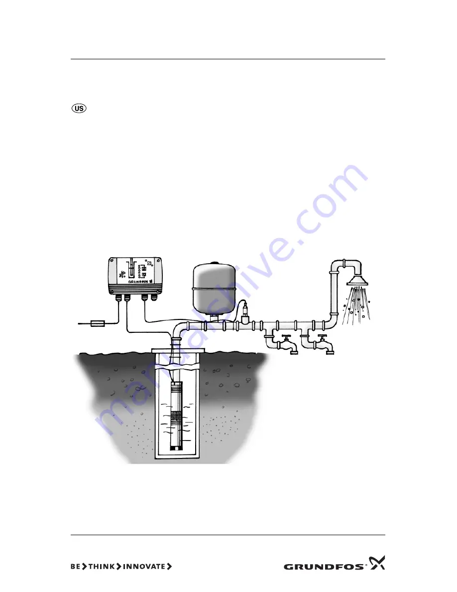
CU 301
GRUNDFOS
INSTRUCTIONS
Installation and operating instructions
Page 1: ...CU 301 GRUNDFOS INSTRUCTIONS Installation and operating instructions...
Page 2: ...under this warranty the defective product must be returned to the distributor or dealer of Grundfos products from which it was purchased together with proof of purchase and installation date failure d...
Page 3: ...3 CU 301 Installation and operating instructions 4...
Page 4: ...ssure 16 5 2 3 Speed 16 5 2 4 Temperature 16 5 2 5 Power input and power consumption 16 5 2 6 Operating hours and number of starts 17 5 3 Menu INSTALLATION 17 5 3 1 Sensor 17 5 3 2 Choice of sensor 17...
Page 5: ...means that no additional cables to the pump are required The communication of data is effected via a high fre quency signal transmitted to the power supply cable and led into the electronics unit by...
Page 6: ...p when no water is consumed the CU 301 per forms flow detection every 10 seconds The pump speed is reduced and pressure is read A pressure drop indicates that water is being con sumed and the pump spe...
Page 7: ...SQE and SQE NE TM01 8547 0400 H ft Q gpm B A Pump curve at 10 700 rpm Pump curve at 3 000 rpm Qrated flow Pump type Min head at 0 gpm 3 000 rpm Max head at rated flow 10 700 rpm feet feet 5 SQE 90 12...
Page 8: ...when the tank volume is limited to 2 gal Use the values in the following table Prechange pressure is measured with 0 psi in the pipeline Note If the precharge pressure is higher than the pressure sett...
Page 9: ...riser pipe shows running light when the pump is operating When the pump is not operating none of the indicator lights are on see fig 9 Fig 9 Indication of pump operation The indication of pump operati...
Page 10: ...ress the arrow down button as the first one when pressing the two buttons Fig 11 Button lock indication When the buttons are locked the indicator light is permanently on see fig 11 For further informa...
Page 11: ...falls below the dry run setting for an accu mulated time of 5 seconds and the motor speed is within 1 000 rpm of the maximum speed setting as defined in the section 5 3 6 the CU 301 stops the pump and...
Page 12: ...minimum speed 3 000 rpm Max speed Permanent yellow light when the pump is running at maximum speed 10 700 rpm Sensor defective Permanent red light when the sensor signal is out of signal range Overloa...
Page 13: ...w button or by removing the front cover and pointing the R100 at the right side of the CU 301 see fig 15 Fig 15 IR communication between the CU 301 and the R100 The R100 offers possibilities of alteri...
Page 14: ...14 Fig 16 Menu overview 5 1 1 5 1 2 5 1 3 5 2 1 5 2 2 5 2 3 5 2 4 5 2 5 5 3 2 5 3 1 5 3 3 5 3 4 5 3 5 5 3 6 5 3 7 5 3 8 5 3 9 5 2 6 5 3 10 0 GENERAL 1 OPERATION 2 STATUS 3 INSTALLATION 5 1 3...
Page 15: ...tion to other displays The Max and Min settings override the pressure setting in display 5 1 1 Pressure setting 5 1 3 Alarm This display shows the current alarm status Possible alarms are described in...
Page 16: ...ured by the pres sure sensor Tolerance 1 5 2 3 Speed The actual speed stated in min 1 rpm Tolerance 1 5 2 4 Temperature The actual temperature of the motor electronics stated in C or F based on langua...
Page 17: ...tual pressure will be identical to the measuring unit in the front cover Exception If Manual is selected in display 5 3 2 Choice of sensor the sensor can be set irre spective of the front cover If cha...
Page 18: ...play Setting range 0 2500 W 10 W intervals Relation to other displays The actual pump power input can be read in display 5 2 5 Power input and power consumption If the maximum pump speed has been redu...
Page 19: ...een each CU 301 control unit motor pair In situations where multiple CU 301 pump power cables are run parallel in wiring trays or conduit and less than 10 12 inches apart the possibility for undesired...
Page 20: ...in the R100 can be printed on a Hewlett Packard printer type HP82240B Navigate the R100 to the print menu and point the R100 at the IR sensor of the printer and press OK The following information will...
Page 21: ...remove the front cover from the CU 301 or use the R100 Fit the front cover as shown in fig 18 to avoid disconnecting the multi core cable A number of LEDs are mounted on the supply board inside the C...
Page 22: ...ssure of the diaphragm tank is incorrect Check that the LED for Max speed or Min speed is on If so this indicates that the pump has reached a limit See section 1 3 System sizing Replace the pump if ne...
Page 23: ...ve Are the three CU 301 supply board LEDs in pos 2 3 and 4 on and is the control indicator LED flashing See section 4 Position of LEDs Yes The mains supply is OK Assign the system a new number If this...
Page 24: ...running stop 9 The CU 301 indi cates Speed reduc tion and Undervoltage Speed reduction is activated so as to maintain a reduced performance When the supply voltage falls so low that it can no longer s...
Page 25: ...4 20 mA measure the DC voltage across the sensor input terminals If the DC voltage measured at the sensor input terminals is not between 2 and 10 V the sensor or wiring is defective Refer to section 9...
Page 26: ...which it will be used If the CU 301 is connected to an electric installation where a Ground Fault Circuit Interrupter GFCI is used as an additional protection this device must trip out when earth faul...
Page 27: ...hes apart the possibility for undesired communication between units exists When this occurs intermittent or continuous No contact is typically seen Other unexpected errors may also be seen Refer to se...
Page 28: ...0 94 5 2 8 14 3 5 4 54 7 8 0 95 2 2 9 15 0 5 5 55 5 8 1 96 0 2 9 15 7 5 5 56 2 8 1 96 7 3 0 16 5 5 6 57 0 8 2 97 5 3 0 17 2 5 6 57 7 8 2 98 2 3 1 18 0 5 7 58 5 8 3 99 0 3 1 18 7 5 7 59 2 8 3 99 7 3 2...
Page 29: ...or parts of it must be disposed of in an environmentally sound way 1 Use the public or private waste collection service 2 If this is not possible contact the nearest Grundfos company or service works...
Page 30: ...3500 Canada GRUNDFOS Canada Inc 2941 Brighton Road Oakville Ontario L6H 6C9 Phone 1 905 829 9533 Telefax 1 905 829 9512 Mexico Bombas GRUNDFOS de Mexico S A de C V Boulevard TLC No 15 Parque Industri...
Page 31: ...www grundfos com Being responsible is our foundation Thinking ahead makes it possible Innovation is the essence L SP TL 019 5 06 US R PRINTED IN USA...