English (GB)
13
7.2.4 Explanation to operating mode
Control enumeration for selection of the remote operating mode.
7.2.5 Setpoint in closed-loop control
Hydro MPC and Multi-E
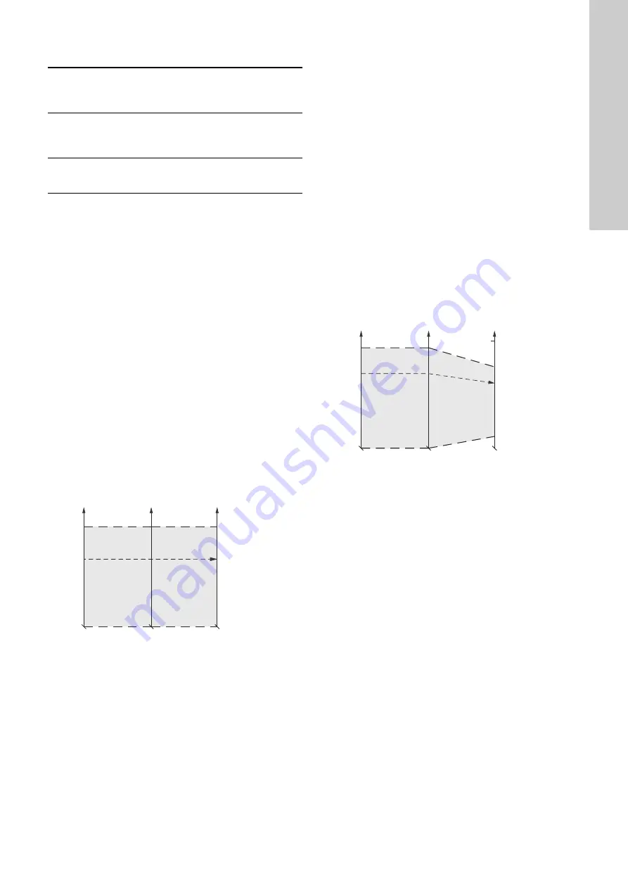
The setpoint is written to module 2 bytes 4 and 5 Setpoint as a
percentage value scaled in 0.01 % of the sensor maximum value,
module 46 FeedbackSensorMax. The sensor minimum value is
always 0. The selected setpoint is reflected in module 41
UserSetpoint with the same scaling.
The actual setpoint, whether it has been set via Grundfos GO
Remote, the pump display, the pump buttons or the fieldbus, can
be read from module 20 ActualSetpoint. It is a percentage value
scaled in 0.01 % of module 46 FeedbackSensorMax.
Generally, the actual setpoint value represents head, pressure,
flow, temperature and so on depending on what the feedback
sensor has been set to measure. The unit of measure can be
read from module 44 FeedbackSensorUnit.
Unless a setpoint influencing function, like proportional influence,
is active, ActualSetpoint equals UserSetpoint.
It is possible to calculate back and forth between the setpoint in
percent and its scaled value:
X
act
[unit] =
X
set
[%]
×
FeedbackSensorMax
×
FeedbackSensorUnit
* Percentage of sensor maximum.
Fig. 17
Setpoint in closed-loop control for Hydro MPC and
Multi-E
TPED and MAGNA3-D
The setpoint is written to module 2 bytes 4 and 5 Setpoint as a
percentage value scaled in 0.01 % of the setpoint range [r
min
;
r
max
]. The selected setpoint is reflected in module 41
UserSetpoint with the same scaling.
The actual setpoint, whether it has been set via Grundfos GO
Remote, the pump display, the pump buttons or the fieldbus, can
be read from module 20 Actua Setpoint. It is a percentage value
scaled in 0.01 % of module 46 FeedbackSensorMax.
Generally, the actual setpoint value represents head, pressure,
flow, temperature and so on depending on what the feedback
sensor has been set to measure. The unit of measure can be
read from module 44 FeedbackSensorUnit.
It is possible to calculate back and forth between ActualSetpoint
in percent and its scaled value:
X
act
[unit] =
X
act
[%]
×
FeedbackSensorMax
×
FeedbackSensorUnit
The setpoint range limits r
min
and r
max
cannot be read from the
fieldbus but can be found in the pump data sheet or they can be
seen in the Grundfos GO Remote "Setpoint" menu.
* Percentage of setpoint range.
** Percentage of sensor maximum.
Fig. 18
Setpoint in closed-loop control for TPED and
MAGNA3-D
0:
AutoControl
This is the normal mode. The booster system is controlled
according to the selected control mode and setpoint.
See section
7.2.3 Explanation to control mode
.
4:
OpenLoopMin
The booster system operates at a fixed minimum
performance.
Note:
Not supported by Hydro Multi-E.
6:
OpenLoopMax
The booster system operates at a fixed maximum
performance.
T
M
07
01
47
43
1
7
X
set
0 %
100 %
X
act
FeedbackSensor
Max (module 46)
Setpoint*
(ControlModule
byte 4 and 5)
UserSetpoint*
(module 41)
ActualSetpoint*
(module 20)
TM
07
01
48
43
17
X
act
FeedbackSensor
Max (module 46)
Setpoint*
(ControlModule
byte 4 and 5)
UserSetpoint*
(module 41)
ActualSetpoint**
(module 20)
r
min
r
max
100 %
X
set
0 %
100 %
Pumpland.ru
Summary of Contents for CIM 150 PROFIBUS DP
Page 34: ...34 Pumpland ru...


