


GRT Avionics, Inc.
May 2019
Sport EX/Horizon EX Install. Manual
15
Rev. A
that a magnet will stick to), control cables or cables carrying electrical currents, such as
navigation o
r landing lights, being too close to the magnetometer. The magnetometer’s
location will be tested for interference in
Section 5: Initial Checkout, Basic
Configuration Settings and Calibration
, after the initial boot-up checks of the Sport EX.
3-3: Cooling Considerations
The GRT Sport EX/Horizon EX do not require external cooling. However, as with all
electronic equipment, lower operating temperatures may extend equipment life. Units in
an avionics stack heat each other through radiation, convection and sometimes by direct
conduction. Even a stand-alone unit operates at a higher temperature in still air than in
moving air. Fans or some other means of moving air around electronic equipment are
usually worthwhile. Be certain that cooling air does not contain water
—a problem often
encountered when using external forced-air cooling methods. A few small openings in the
glare shield are usually enough for adequate natural air circulation.
3-4: Pitot-Static Connections
The PFD display unit also contains the Air Data Computer. The ADC requires connection
to the aircraft
’s pitot-static system. Connections on the display unit take a 1/8 – 27 NPT
male fitting. To facilitate installation and removal of the display unit, quick disconnect
fittings may be helpful. Connections and the entire pitot-static system must be leak-tight.
Refer to AC 43.13-2B for approved methods to achieve this.
Consider placing a water trap or drain in the lowest part of the pitot-static system to
prevent water from getting into the electronics. Make sure the drain is of a high enough
quality that it seals completely airtight when closed.
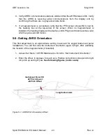
3-5: Angle-of-Attack Pressure Port Connection
When equipped with the sensed angle-of-attack (AOA) option, the pitot-static block will
also include a port for sensing the AOA using a dual port pitot tube. This type of pitot tube
provides the pitot pressure for sensing indicated airspeed and a second pitot pressure for
sensing AOA. Typically, this AOA pitot is positioned about 60° down from the pitot used
to sense indicated airspeed. This probe is available from several third-party sources, or
may be fabricated by the builder by adding a second pitot tube, bent to point 60° below
the pitot used for airspeed. When constructing your own AOA pitot, it should be mounted
as close as practical to the airspeed pitot.
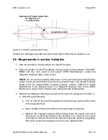
Use the appropriate tubing to make an air-tight connection between the AOA pitot and
the AOA port on the EFIS. The AOA port is located between the P
itot (marked “P”) and
the Static (marked
“S”) ports.


