background image


编号:

GR-UM-C -00 


1

 / 

57


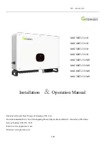
Installation   

Operation Manual 


Shenzhen Growatt New Energy Technology CO., Ltd 

Growatt Industrial Park, No.28 Guangming Road, Shiyan, Baoan District , Shenzhen, P.R.China. 

Service hotline: 400-931-3122 

Email[email protected] 

Website: www.growatt.com


MAC 30KTL3-X LV 

MAC 40KTL3-X LV 

MAC 50KTL3-X LV


MAC 60KTL3-X LV   

MAC 50KTL3-X MV 

MAC 60KTL3-X MV 

MAC 66KTL3-X MV 

MAC 70KTL3-X MV 


Summary of Contents for MAC 30KTL3-X LV

Page 1: ...rowatt Industrial Park No 28 Guangming Road Shiyan Baoan District Shenzhen P R China Service hotline 400 931 3122 Email service ginverter com Website www growatt com MAC 30KTL3 X LV MAC 40KTL3 X LV MA...

Page 2: ...3 6 Grid Type 9 4 Unpacking 10 5 Installation 11 5 1 Basic Installation Requirements 11 5 2 Installation Environment Requirements 13 Moving Requirements 14 5 4 Wall Mount Bracket Installation 14 Figur...

Page 3: ...Setting 29 8 Monitoring Method 31 8 1 Remote Data Monitoring 31 8 1 1 Mobile APP ShinePhone remote monitoring 31 8 1 2 Server WEB webpage remote monitoring ShineGPRS X 35 8 2 Local Data Monitoring 39...

Page 4: ...message or call 24 hours consumer service hotline 400 931 3122 2 Safety Precautions 2 1 Safety Overview 1 Before installation please make sure reading through this manual any damage caused by imprope...

Page 5: ...shocks and serious injury please do not touch the inverter Please do not store inverter in area with flammable and explosive material WARNING Each inverter must install one AC breaker AC breaker is f...

Page 6: ...CAUTION Indicates potentially hazardous situation which if not avoided will result in minor or moderate injury NOTICE Indicates certain hazardous situation which if not avoided will result in propert...

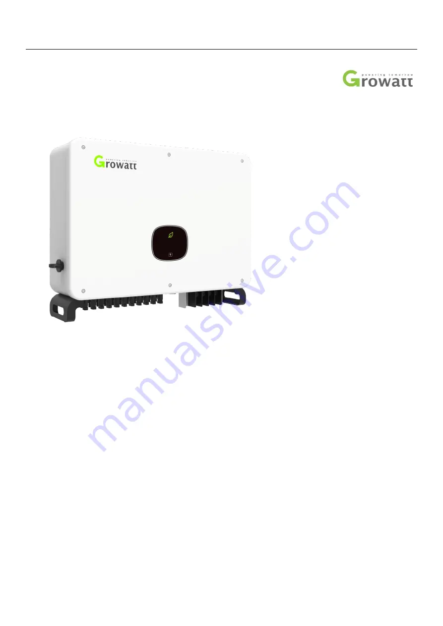
Page 7: ...r DC side AC Means this terminal is for AC side 3 Product Introduction 3 1 Appearance Front view Mark Description Mark Description A DC switch G 485 Waterproof connector B Fan H AC Waterproof connecto...

Page 8: ...to the nameplate shown above but the product model and specific parameters are different See Chapter 10 Product Specifications for specific parameters Identification Description Explanation Touch mark...

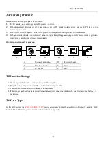
Page 9: ...tion relay can disconnect inverter immediately On grid connection system diagram 3 5 Inverter Storage 1 Do not unpack the Inverter and store it in a ventilation dry place 2 Keep the storage temperatur...

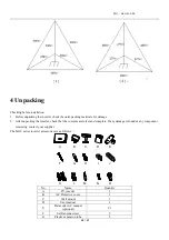
Page 10: ...that the contents are intact and complete If any damage is found or any component is missing contact your supplier The MAC series inverter accessories are as follows No Name Quantity A PV inverter 1...

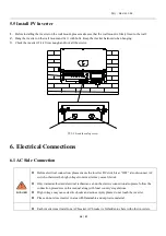
Page 11: ...or any other object because the terminals are not designed to support the weight of inverter When placing inverter on the floor put foam or paper under the inverter to protect its cover 5 1 Basic Inst...

Page 12: ...e ground must be more than 1 meter Figure 5 1 Installation diagram J To ensure the inverter can work smoothly and easy for personnel to operate please notice there is sufficient space for inverter ref...

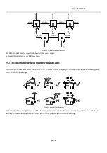
Page 13: ...inverter lifespan you still need to avoid rain and snow please refer to following drawings Figure 5 4 install environment B To reduce the de rate performance of the inverter and extend inverter s lif...

Page 14: ...ontacting with floor or any other object because the terminals are not designed to support the weight of inverter 1 2 3 people put their hands into the package lift the inverter out of the package and...

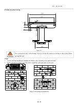
Page 15: ...e sure to check the wall for power lines or other piping before opening the wall Steps 1 Use the wall mount plate as a template drill holes on the wall and put in expansion bolts 2 Follow the followin...

Page 16: ...ER Before electrical connection please ensure the inverter DC switch is at OFF also disconnect AC switch otherwise the high voltage from inverter may cause life risk Only trained authorized electrical...

Page 17: ...c MAC 66KTL3 X MV 100A 480Vac MAC 70KTL3 X MV 100A 480Vac Cable specifications refer to the following table PV inverter Cross sectional area mm2 Recommended value mm2 Copper wire Aluminum wire Copper...

Page 18: ...t OFF also disconnect AC switch otherwise the high voltage from inverter may cause life risk Only trained authorized electrical technician can do the electric connection also please follow the connect...

Page 19: ...s good The picture shows the connection of the DC terminal Notice Connectors need to be fit with male and female terminals before connecting panels with inverter please make sure the positive pole and...

Page 20: ...cation Connection 6 3 1 RS485 The MAC series comes standard with two RS485 interfaces and you can monitor one or more inverters via RS485 Another RS485 port is used to connect the smart meter single m...

Page 21: ...nded to switch the DIP switch 2 of the last inverter from the left side to the right side to introduce a matching resistor Refer to the following figure for wiring 6 3 2 USB The USB port is mainly use...

Page 22: ...und Single inverter need grounding over a PE point multiple inverters need connect all the inverter PE cable and solar panels shelves to the same grounding point to achieve equipotential Note Pay atte...

Page 23: ...the position of the picture Normally the Type II should be installed at the recommended position and the Type 3 should be installed with the TypeI B When the safety and safety distance S is not met In...

Page 24: ...the inverter is connected by RS485 and multi machine parallel communication the inverter should be set to different communication address when the single machine communicates the factory default commu...

Page 25: ...ional 1 Click Settings in device list to enter the advanced settings page 2 Read the 30 register to get the current device address the password is max today date such as August 7th max20190807 3 When...

Page 26: ...Time and Date Refer to Section 8 2 1 to log in to the mobile APP After the mobile phone communicates normally with the inverter through the APP click Parameter Configuration and select System Time 45...

Page 27: ...odule DC to the grid When the DC voltage is lower than 250VDC inverter will enter into waiting and try to connect to the grid at this status inverter consume very small power to check the internal sys...

Page 28: ...ng status of the inverter and various parameter information The touch panel can be used to switch the display interface of the inverter and set the inverter parameters Touch mode definition single Swi...

Page 29: ...onsecutive touches three consecutive touches and long press 5S Different types of taps have different functions Advanced setup password 111 Touch mode definition single Move turn page or current numbe...

Page 30: ...vels Excessive voltage of the power grid may affect the normal use and service life of the household appliances on the grid side or cause loss of power generation Due to the related effects and conseq...

Page 31: ...12 30 30 Set OK Set OK Set Comaddr 1 Set Language English General Advanced Set Parameter 8 Monitoring Method 8 1 Remote Data Monitoring MAC series inverter remote data monitoring methods include mobi...

Page 32: ...istration page and main interface are as shown below ShinePhone Main interface 1 The center of the main interface shows the current power station name You can switch between different power stations i...

Page 33: ...station name Way click on the top right corner to add datalogger WiFi GPRS etc as 7 1 1 02 Note If add wifi datalogger will need to configure it manually scan the wifi datalogger for 2 seconds until...

Page 34: ...the icon below the interface 2 Control user set inverter on off set active power set reactive power set PF set inverter time set grid voltage high set grid voltage low The operation password is invert...

Page 35: ...1 Register account Open browser input server growatt com click New User at login page input the necessary information then go back to login page input the registered username and password click login...

Page 36: ...GR UM C 00 36 57 datalogger will show after 5mins also the device will come online The inverter is monitored by the collector so the collector can be added...

Page 37: ...Information A Click on Dashboard to view related information such as Day of Power Generation Cumulative Power Generation Today s revenue and Total revenue B Click plant and Plant data to view the inve...

Page 38: ...led data Click Plant device list MAX MID and the inverter list of the power station is displayed Double click on the inverter name in the list to display the detailed data of the inverter The data can...

Page 39: ...nnect the DC switch and AC switch and wait for at least 5 minutes until internal capacitance discharge completely 1 Check the ambient temperature and dust of the inverter clean the inverter when neces...

Page 40: ...n to reduce the internal temperature When the inverter is derating because of the internal temperature is too high the following are the possible reasons or solutions 1 Fan is blocked or the heat sink...

Page 41: ...dentify the current status of the inverter Max warnings do not related to a fault and it does not affect the normal running of the inverter When a warning with a number after it appears in the display...

Page 42: ...2 2 Error Errors codes identify a possible equipment failure fault or incorrect inverter setting or configuration any or all attempts to correct or clear a fault must be performed by qualified personn...

Page 43: ...ct manufacturer Error 409 Bus voltage abnormal 1 Restart inverter 2 If error message still exists contact manufacturer Error 411 Communication fault 1 After shutdown Check communication board wiring 2...

Page 44: ...MPP trackers 3 3 2 3 3 3 4 3 3 4 4 4 Output Data AC AC nominal power 30000W 40000W 50000W 60000W Max AC apparent power 33300VA 44400VA 55500VA 66600VA Nominal AC voltage range 230V 400V 340 440V AC 23...

Page 45: ...ption night 1W Topology Transformerless Cooling concept Fan cool Environmental Protection Rating IP65 Warranty 5 years 10years Option Certificates and approvals Safety EMC EN 61000 3 EN 61000 6 EN IEC...

Page 46: ...id frequency range 50 60 Hz 45 55Hz 55 65 Hz Max output current 60 2A cos 1 66 9A cos 0 9 72 2A cos 1 80 2A cos 0 9 79 4A cos 1 88 2A cos 0 9 84 2A cos 1 93 6A cos 0 9 Power factor nominal power 0 99...

Page 47: ...vals Safety EMC EN 61000 3 EN 61000 6 EN IEC 62109 1 EN IEC 62109 2 IEC 60529 11 Decommissioning If the inverter does not operate in the future it needs to be properly disposing The steps are as follo...

Page 48: ...rter type 2 Serial number of inverter 3 Error code of inverter 4 LED status of inverter 5 DC input voltage of inverter Modules information 6 Inverter communication method Growatt New Energy Technology...

Reviews: