


GLDM 64.1 Technical Manual rev. 1.30 February
2020
Page 8 of 50
GLDM
64.1
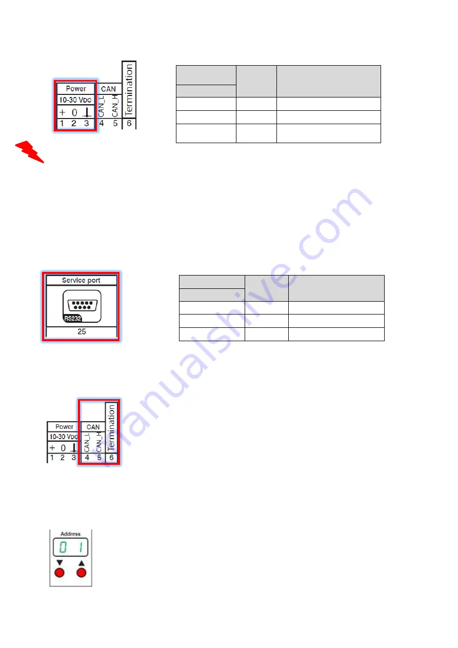
Power in
Function
Pin no.
1
+
Power 10...30 V DC
2
-
Common ground / 0 V DC
3
Shld
.
Chassis ground
GLDM 64.1
RS 232
Functi
on
Pin no.
3
Rx
Receive Data
2
Tx
Transmit Data
5
GND
Signal ground RS 232
3.4. Terminals Power Supply
Depending on the grounding concept of the plant/scale, terminal 2 has to be connected to terminal 3.
Terminal 11 (shld. load cell) and 3 (Ground chassis) are internal connected.
Note: The power supply must be able to supply about 0.75W per GLDM 64.1.
3.5. Service Port RS 232
The service port RS 232 can be used for communication with a PC or PLC system, in parallel to the
CAN open interface.
The serial port supports ASCII Protocol.
3.6. CANbus Interface
The CANbus interface can be used for communication in a CANopen network
with transmission speed 10 ... 1000 kbit/s.
- The CAN lines CANH (5) and CANL (4) can be connected to a CANopen
master.
-
Termination resistors must be present in the CAN network. A 120 Ω resistor
inside the GLDM 64.1 can be switched ON/OFF (using jumper 6).
-
When used with the Gateway EGM 187.1, one 120Ω termination resistor is
present inside the gateway. The last GLDM on the CAN bus must also
have its termination resistor connected.
The factory default settings for communication are
address 1
and
transmission speed
500 kbit/s
.
Note
: CANopen communication profile is described in this manual, see chapter 9 (pages 39 ff).
For changing the CAN address via front panel, just use the
Up/Down buttons below the Address display.