


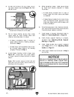


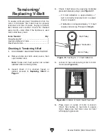


Figure 36. Upper blade guide assembly (blade
guard removed).
Figure 35. Lower blade guide support bearing
(table removed).
Model T32304 (Mfd. Since 02/21)
-27-
Lower Blade Support Bearing:
1. DISCONNECT MACHINE FROM POWER!
2. Remove table.
Note:
Fence and meat pusher can remain
installed when removing table.
3. Loosen support bearing adjustment screw
(see
Figure 35).
4. Position support bearing approximately
1
⁄
32
"
away from back of blade.
5. Tighten support bearing adjustment screw.
6. Re-install table removed in Step 2.
Adjustment
Screw
Support
Bearing
IMPORTANT: Verify blade is tracking and ten-
sioned correctly before performing this procedure
(see
Tensioning Blade on Page 25).
Tools Needed
Qty
Hex Wrench 5mm ............................................... 1
To adjust blade guides:
1. DISCONNECT MACHINE FROM POWER!
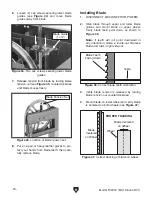
2. Remove blade guard.
3. Loosen (2) guide adjustment screws (see
Figure 36), adjust blade guides approximate-
ly 0.004" (about the thickness of a dollar bill)
away from blade, and tighten screws.
Adjusting Blade
Guides
The upper blade guides (see
Figure 36) can be
adjusted left-to-right, as well as front-to-back, rel-
ative to the blade. Properly adjusted blade guides
provide side-to-side support, from just behind the
gullets to the back of the blade, to help keep the
blade straight while cutting.
Blade Guide
(1 of 2)
Upper
Blade Guide
Assembly
Guide
Adjustment
Screws
Summary of Contents for T32304
Page 52: ......