background image

MODEL G1095/G1096 

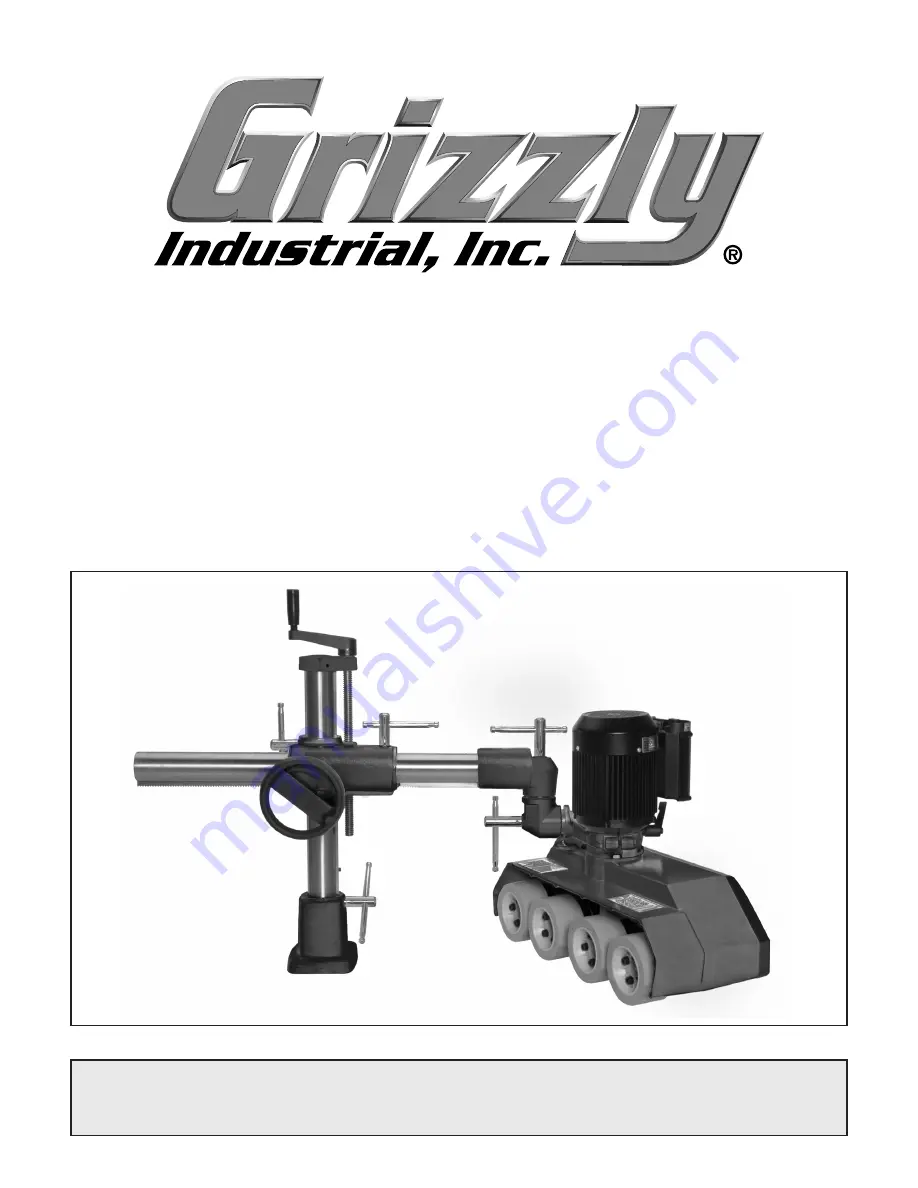
1-HP POWER FEEDER

with 4-ROLLER & 4-SPEED

OWNER'S MaNuaL

Copyright © MAy, 2008 By grizzly industriAl, inC.

WaRNiNG: NO PORtiON OF tHiS MaNuaL May bE REPRODucED iN aNy SHaPE

 OR FORM WitHOut tHE WRittEN aPPROvaL OF GRizzLy iNDuStRiaL, iNc.

 #Cr10667  printed in tAiWAn

Summary of Contents for G1095

Page 1: ... with 4 ROLLER 4 SPEED OWNER S Manual Copyright MAY 2008 By Grizzly Industrial Inc Warning No portion of this manual may be reproduced in any shape Or form without the written approval of Grizzly Industrial inc CR10667 printed IN TAIWAN ...

Page 2: ...PERSONAL PROTECTIVE EQUIPMENT 4HE MANUFACTURER WILL NOT BE HELD LIABLE FOR INJURY OR PROPERTY DAMAGE FROM NEGLIGENCE IMPROPER TRAINING MACHINE MODIFICATIONS OR MISUSE 3OME DUST CREATED BY POWER SANDING SAWING GRINDING DRILLING AND OTHER CONSTRUCTION ACTIVITIES CONTAINS CHEMICALS KNOWN TO THE 3TATE OF ALIFORNIA TO CAUSE CANCER BIRTH DEFECTS OR OTHER REPRODUCTIVE HARM 3OME EXAMPLES OF THESE CHEMICAL...

Page 3: ...G1096 12 SECTION 3 SETUP 13 Setup Safety 13 Items Needed for Setup 13 Unpacking 13 Inventory 14 Clean Up 15 Assembly 15 Base Mounting 16 Test Run 18 SECTION 4 OPERATIONS 19 Operation Safety 19 Basic Use and Care 19 Changing Speeds 20 SECTION 5 MAINTENANCE 21 Schedule 21 Cleaning 21 Lubrication 21 SECTION 6 SERVICE 22 Troubleshooting 22 Wheel Replacement 23 SECTION 7 WIRING 24 Electrical Safety Ins...

Page 4: ...e to us at the address below Grizzly Industrial Inc C O Technical Documentation Manager P O Box 2069 Bellingham WA 98227 2069 Email manuals grizzly com Contact Info This power feeder greatly simplifies repetitive operations on table saws jointers and shapers by automating how workpieces are fed into the cut This is extremely important to woodshops that cut thousands of board feed on a regular basi...

Page 5: ... 4 x 23 1 2 x 29 1 2 in Foot Print Length Width N A x N A H ee c 9 bZch dch 8Vgidc Type Cardboard Content Machine Weight 71 lbs Length Width Height 30 x 12 x 22 in 8Vgidc Type Cardboard Content Stand Weight 79 lbs Length Width Height 30 x 13 x 11 in aZXig XVa Switch Forward Reverse Switch Voltage 220V Cord Length 9 ft Cord Gauge 16 gauge Recommended Breaker Size 10 amp Plug No Bdidgh BV c Type TEF...

Page 6: ...s 4 Roller Width 2 3 8 in Roller Diameter 4 3 4 in Roller Suspension 3 4 in Max Hght Rollers Parallel Table Surface 8 1 2 in Centers Between Rollers 5 in Other Column Diameter 2 1 4 in Construction Info Roller Construction Synthetic Rubber Housing Construction Cast Aluminum Supports Construction Cast Iron Column Construction Steel Paint Epoxy Other Specifications ISO Factory ISO 9001 Country Of Or...

Page 7: ... 29 1 2 in Foot Print Length Width N A x N A H ee c 9 bZch dch 8Vgidc Type Cardboard Content Machine Weight 70 lbs Length Width Height 30 x 12 x 22 in 8Vgidc Type Cardboard Content Stand Weight 80 lbs Length Width Height 30 x 13 x 11 in aZXig XVa Switch Forward Reverse Switch Voltage 220V Cord Length 9 ft Cord Gauge 16 gauge Recommended Breaker Size 10 amp Plug No Phase Converter G5841 Bdidgh BV c...

Page 8: ...s 4 Roller Width 2 3 8 in Roller Diameter 4 3 4 in Roller Suspension 3 4 in Max Hght Rollers Parallel Table Surface 8 1 2 in Centers Between Rollers 5 in Other Column Diameter 2 1 4 in Construction Info Roller Construction Synthetic Rubber Housing Construction Cast Aluminum Supports Construction Cast Iron Column Construction Steel Paint Epoxy Other Specifications ISO Factory ISO 9001 Country Of Or...

Page 9: ...nd features Motor Assembly Rotary Movement Lock Vertical Travel Lock Lower Elbow Joint Lock Upper Elbow Joint Lock Power Feeder Swivel Lock Refer to Figure 1 and your power feeder to familiarize yourself with the controls features and terminology used in this manual Doing so will make setup use and any future maintenance easy Gearbox Oil Plug ...

Page 10: ...3AFETY 2EAD NSTRUCTION ANUAL EFORE PERATING THIS ACHINE 4HE PURPOSE OF SAFETY SYMBOLS IS TO ATTRACT YOUR ATTENTION TO POSSIBLE HAZARDOUS CONDITIONS 4HIS MANUAL USES A SERIES OF SYMBOLS AND SIGNAL WORDS INTENDED TO CONVEY THE LEVEL OF IMPORTANCE OF THE SAFETY MESSAGES 4HE PROGRESSION OF SYMBOLS IS DESCRIBED BELOW 2EMEMBER THAT SAFETY MESSAGES BY THEMSELVES DO NOT ELIMINATE DANGER AND ARE NOT A SUBS...

Page 11: ...higjXi dch dg ajWg XVi c VcY X Vc c VXXZhhdg Zh 352 5 2 3 2 0 7 2 22 4 9 2 53 29 3AFETY NSTRUCTIONS FOR ACHINERY 2 6 534 93 72 3 BV Z V VW i d X ZX c dg Znh VcY VY_jhi c lgZcX Zh WZ dgZ ijgc c bVX cZgn 2 0 243 2 53 29 8 ZX dg W cY c dg b hVa cZY eVgih Wgd Zc eVgih addhZ Wdaih VcY Vcn di Zg XdcY i dch i Vi bVn beV g bVX cZ deZgVi dc GZeV g dg gZeaVXZ YVbV ZY eVgih WZ dgZ deZgVi dc 53 2 33 2 3 GZ Zg...

Page 12: ...ad the cutting tool by feeding too quickly The cutting tool will perform better and be safer working at the rate for which it was designed 4 HAND SAFETY Keep hands away from rotating parts on the feeder and the cut ting tool Do not allow hands or clothing to be pinched beween the rollers and workpiece No list of safety guidelines can be complete Every shop environment is different Always consider ...

Page 13: ...ce the machine near a power source If you must use an extension cord Use at least a 14 gauge cord that does not exceed 50 feet in length The extension cord must also have a ground wire and plug pin A qualified electrician MUST size cords over 50 feet long to prevent motor damage Figure 2 NEMA 6 15 plug and receptacle SECTION 2 CIRCUIT REQUIREMENTS Serious personal injury could occur if you connect...

Page 14: ...ion cords may reduce the life of the motor Instead place the machine near a power source If you must use an extension cord Use at least a 16 gauge cord that does not exceed 50 feet in length Ensure that the extension cord contains a ground wire and plug pin Serious personal injury could occur if you connect the machine to power before com pleting the setup process DO NOT connect the machine to the...

Page 15: ...stem 1 4 Dust Hose 1 Items Needed for Setup Your machine was carefully packaged for safe transportation Remove the packaging materials from around your machine and inspect it If you discover the machine is damaged please imme diately call Customer Service at 570 546 9663 for advice Save the containers and all packing materials for possible inspection by the carrier or its agent Otherwise filing a ...

Page 16: ...es 4 5 Qty A Power Feeder Assembly 1 B Lubricator 1 C Base and Column Assembly 1 D Elbow Joint Assembly 1 E Base Bolt Pattern Template 1 F Handwheel Handle 1 G Horizontal Column Assembly 1 If any nonproprietary parts are missing e g a nut or a washer we will gladly replace them or for the sake of expediency replacements can be obtained at your local hardware store SUFFOCATION HAZARD Immediately di...

Page 17: ...Model G1095 G1096 1 HP Power Feeder 15 Hardware Recognition Chart ...

Page 18: ...ean the machinery Many cleaning solvents are toxic if inhaled Minimize your risk by only using these products in a well ventilated area G2544 Solvent Cleaner Degreaser A great product for removing the waxy shipping grease from your machine during clean up Figure 6 Cleaner degreaser available from Grizzly Figure 8 Assembled power feeder Figure 7 Item installation order To correctly position this po...

Page 19: ...andwheels and lock levers to position the rubber wheels parallel with the table surface and 1 8 lower than the thickness of your workpiece Also you must be able to point the power feeder slightly towards the machine fence Figure 9 In other words the tracking of the power feeder must be toed in approximately 1 to 1 5 degrees toward the machine fence so the rubber wheels slightly push the workpiece ...

Page 20: ...ads Figure 10 Through bolt mounting Machine Table aVi LVh Zg aVi LVh Zg AdX LVh Zg AdX c Zm Cji IVWaZ Hjeedgi LZWW c 7dai Feeder Base Figure 11 Direct mounting Machine Table IVWaZ Hjeedgi LZWW c 7dai Feeder Base AdX LVh Zg aVi LVh Zg 6eean V BZY jb gVYZ I gZVY AdX c 8dbedjcY id i Z I gZVYh Through Bolt Mounting We recommend that you mount your new power feeder to the machine table with through bol...

Page 21: ...oil fill port location 3 Ensure that all tools and objects used during set up are cleared away from the machine Loose hair and clothing could get caught in machinery and cause serious personal injury Keep loose clothing rolled up and long hair tied up and away from machin ery Figure 12 Feed direction and speed dial 4 Adjust and lock the power feeder so the wheels are held approximately one inch ab...

Page 22: ...kickback When not in use support the power feeder with a wooden block so the rubber wheels are raised above the table and do not compress from the weight of the power feeder The lock levers and handcranks on this power feeder allow you to adjust the power feeder track ing and height to accommodate many workpiece sizes Before loosening any lock lever always support the power feeder with a block of ...

Page 23: ...connect power to the machine before performing installation or maintenance Failure to do this may result in serious personal injury 26 Ft Per Min A 40 Tooth B 25 Tooth 33 Ft Per Min A 25 Tooth B 40 Tooth 66 Ft Per Min A 40 Tooth B 25 Tooth Motor OFF 13 Ft Per Min A 25 Tooth B 40 Tooth 3 Refer to the feed rate list below to find the gear combination required for your chosen feed rate 4 Remove the c...

Page 24: ...ag and a mild solvent Avoid touching the plastic or paint with mineral spirits or you may damage the surfaces Lubrication Every 40 hours of use or once every two weeks wipe clean and lubricate the wheel grease fittings Figure 15 with one pump of an automotive grade multipurpose grease Do not get any grease on the rubber wheels Figure 15 Wheel lubrication Grease Fitting Figure 16 Lubrication locati...

Page 25: ...tor overheats 1 Motor overloaded 2 Air circulation through the motor restricted 1 Reduce power feeder feed rate 2 Clean out motor fan cover to provide normal air circulation Workpiece jams when feeding under rollers 1 Rollers set too low 2 Feeder at wrong angle 1 Raise feeder 2 Adjust angle Workpiece slips while passing beneath rollers 1 Rollers positioned too high no traction 2 Feeding too fast 3...

Page 26: ...l retaining cap screws Figure 17 Wheel Replacement Always disconnect power to the machine before performing installation or maintenance Failure to do this may result in serious personal injury 3 Swap the old wheel with the new one 4 Reinstall the four cap screws and tighten in an alternating pattern until the wheel is tight Figure 17 Wheel cap screws Cap Screw ...

Page 27: ...6 9663 for assistance 2 CIRCUIT REQUIREMENTS You MUST follow the circuit requirements given on Page 11 or 12 If you are unsure about the wiring codes in your area or you plan to connect your machine to a shared cir cuit consult a qualified electrician 3 SHOCK HAZARD Disconnect the power from the machine before servicing electri cal components Touching electrified parts will result in personal inju...

Page 28: ...and capacitor front view Figure 18 Motor switch side view BdYZa EdlZg ZZYZg K H c aZ E VhZ L g c 9 V gVb Ild HeZZY Bdidg 9 gZXi dc Hl iX gdjcY K Ild HeZZY Bdidg B 9 K68 H YZ 6 H YZ 7 J N K L O I H G 8VeVX idg di di Eaj 6h GZXdbbZcYZY View this page in color at www grizzly com ...

Page 29: ... Hl iX gdjcY K Ild HeZZY Bdidg H YZ 6 H YZ 7 J N K L O I H G gdjcY di L O M di di BdYZa EdlZg ZZYZg K I gZZ E VhZ L g c 9 V gVb K Zl i h eV Z c Xdadg Vi lll g ooan Xdb K K68 E VhZ Eaj 6h GZXdbbZcYZY Figure 21 Motor switch front view Figure 20 Motor switch side view ...

Page 30: ... 28 Model G1095 G1096 1 HP Power Feeder SECTION 8 PARTS Dcan Main Power Feeder Assembly ...

Page 31: ...G1095 117 P1096117 TUBE P1096170 MOTOR 220V 2 SPD 3 PH G1096 118 PR58M EXT RETAINING RING 24MM 170 1 P1096170 1 SWITCH W ELECTRICAL BOX 119 P1096119 SPROCKET SHAFT 170 2 P1096170 2 BOX COVER 120 PR47M EXT RETAINING RING 13MM 170 3 P1096170 3 FAN COVER 122 PW01 FLAT WASHER 1 2 170 4 P1095170 4 MOTOR FAN G1095 123 PN09M HEX NUT M12 1 75 P1096170 4 MOTOR FAN G1096 124 P1096124 GREASE FITTING 170 5 PC...

Page 32: ...TUBE CONE 206 P1096206 VERTICAL COLUMN 234 PRP71M ROLL PIN 6 X 22 207 P1096207 GUIDE 240 P1096240 SWIVEL CLAMP CONE 210 P1096210 HORIZONTAL TUBE 241 P1096241 LOCK STUD 212 PSB50M CAP SCREW M5 8 X 10 251 P1096251 HANDLE 214 P1096214 ELEVATING BRACKET 252 P1096252 POINTED SET SCREW M8 1 25 x 12 218 P1096218 VERTICAL LEAD SCREW 254 P1096254 CRANK ARM 219 PSS09M SET SCREW M8 1 25 X 20 255 PRP32M ROLL ...

Page 33: ...TT TTTT TTTT TTTT TTTT L Vi h ndjg V Z gdje4 TTTT TTTT TTTT TTTT TTTT TTTT dl adc VkZ ndj WZZc V lddYldg Zg bZiValdg Zg4 TTTT NZVgh TTTT NZVgh TTTT NZVgh TTTT NZVgh dl bVcn d ndjg bVX cZh dg iddah VgZ g ooan4 TTTT TTTT TTTT TTTT 9d ndj i c ndjg bVX cZ gZegZhZcih V ddY kVajZ4 TTTTTNZh TTTTTCd LdjaY ndj gZXdbbZcY g ooan cYjhig Va id V g ZcY4 TTTTTNZh TTTTTCd LdjaY ndj Vaadl jh id jhZ ndjg cVbZ Vh V ...

Page 34: ...DI HI6EA DA9 6ADC 9DII 9 A C DA9 6ADC 9DII 9 A C 2 9 5342 0 8 7 EaVXZ HiVbe ZgZ CVbZTTTTTTTTTTTTTTTTTTTTTTTTTTTTTTT HigZZiTTTTTTTTTTTTTTTTTTTTTTTTTTTTTTT 8 inTTTTTTTTTTTTTTHiViZTTTTTTO eTTTTTT HZcY V g ooan 8ViVad id V g ZcY ...

Page 35: ...n h Vaa WZ ig ZY c i Z HiViZ d LVh c idc 8djcin d L ViXdb LZ h Vaa c cd ZkZci WZ a VWaZ dg YZVi c_jg Zh id eZghdch dg egdeZgin dg dg cX YZciVa Xdci c Zci heZX Va dg XdchZfjZci Va YVbV Zh Vg h c gdb i Z jhZ d djg egdYjXih Id iV Z VYkVciV Z d i h lVggVcin XdciVXi jh Wn bV a dg e dcZ VcY kZ jh Vaa i Z YZiV ah LZ l aa i Zc hhjZ ndj V GZijgc CjbWZg l X bjhi WZ XaZVgan edhiZY dc i Z djih YZ Vh lZaa Vh i...

Page 36: ...IRECT AND 3AVE WITH RIZZLY n 4RUSTED 0ROVEN AND A REAT 6ALUE 2 s 3 52 2 2 s 2 23 3 00 7 4 523 s 2 30 3 7 4 52 6ISIT UR 7EBSITE 4ODAY ND ISCOVER 7HY RIZZLY S 4HE NDUSTRY EADER ALL 4ODAY OR 2 ULL OLOR ATALOG ...

Reviews: