


-4-
Model G1014Z/G1014ZX (Mfd. Since 08/22)
Controls &
Components
To reduce your risk of
serious injury, read this
entire manual BEFORE
using machine.
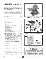
Power Controls
Refer to the following figures and descriptions to
become familiar with the basic controls and com-
ponents of this machine. Understanding these
items and how they work will help you understand
the rest of the manual and minimize your risk of
injury when operating this machine.
Figure 1. Paddle switch location on G1014Z.
A. Paddle Switch: Turns the motor ON when
flipped up; turns motor
OFF when pressed
down.
B. Switch Disabling Key: Disables switch when
the yellow key is removed.
Figure 2. Paddle switch location on G1014ZX.
A
B
A
B
Table Controls
Figure 3. Table tilt controls.
C. Miter Gauge: Moves workpieces into the
sanding disc (horizontal sanding) or belt (ver-
tical sanding) at a specific angle. Slide miter
gauge into the miter slot, loosen the lock
knob, set the angle, then tighten the knob.
D. Table Tilt Lock Knob: Loosens to tilt the
table relative to the sanding disc or the sand-
ing belt, then tightens to secure.
C
D
Sanding Belt Controls
E. Sanding Belt Frame: Tilts between horizon-
tal and vertical positions.
F. Tracking Control Knob: Adjusts belt track-
ing on the rollers. Loosen the lock nut on the
tracking knob, turn the motor
ON, adjust the
tracking in small increments with the knob,
then tighten the lock nut to secure.
G. Quick Release Tension Lever: Tensions the
sanding belt when moved toward the motor.
Figure 4. Sanding belt controls.
E
G
F


