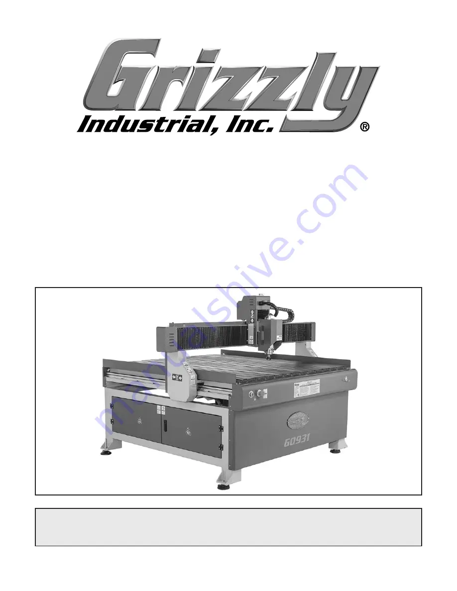
Grizzly G0931 Owner'S Manual Download Page 1

MODEL G0931

47" X 47" CNC ROUTER

w/T-SLOT TABLE

OWNER'S MANUAL

(For models manufactured since 02/21)

COPYRIGHT © APRIL, 2022 BY GRIZZLY INDUSTRIAL, INC.


WARNING: NO PORTION OF THIS MANUAL MAY BE REPRODUCED IN ANY SHAPE

 OR FORM WITHOUT THE WRITTEN APPROVAL OF GRIZZLY INDUSTRIAL, INC.

#KS22105 PRINTED IN CHINA

V1.04.22

***Keep for Future Reference***

Summary of Contents for G0931

Page 1: ...models manufactured since 02 21 COPYRIGHT APRIL 2022 BY GRIZZLY INDUSTRIAL INC WARNING NO PORTION OF THIS MANUAL MAY BE REPRODUCED IN ANY SHAPE OR FORM WITHOUT THE WRITTEN APPROVAL OF GRIZZLY INDUSTRIAL INC KS22105 PRINTED IN CHINA V1 04 22 Keep for Future Reference ...

Page 2: ...ng grinding tool integrity and the usage of personal protective equipment The manufacturer will not be held liable for injury or property damage from negligence improper training machine modifications or misuse Some dust created by power sanding sawing grinding drilling and other construction activities contains chemicals known to the State of California to cause cancer birth defects or other repr...

Page 3: ... Clamping Workpiece 28 Using a Spoilboard 28 Adjusting Axis Positions Manually 29 Homing Axes 30 Setting Origin 30 Creating G Code File 31 Uploading Running G Code 32 Changing Advanced Settings 33 Using Advanced Controls 34 Manually Setting Spindle Speed 34 SECTION 5 ACCESSORIES 35 SECTION 6 MAINTENANCE 38 Schedule 38 Cleaning Protecting 38 Lubrication 38 Coolant 41 SECTION 7 SERVICE 42 Troublesho...

Page 4: ...uc tions specifications drawings and photographs in this manual Sometimes we make mistakes but our policy of continuous improvement also means that sometimes the machine you receive is slightly different than shown in the manual If you find this to be the case and the difference between the manual and machine leaves you confused or unsure about something check our website for an updated version We...

Page 5: ...nder stand the instructions in this manual Table ON Button Spindle Motor X Axis Y Axis Z Axis Power Connection Cable Carrier Z Axis Tool Setter EMERGENCY STOP Button Y Axis Stepper Motor Behind Cover Z Axis Stepper Motor Behind Cover X Axis Stepper Motor Behind Cover Electrical Cabinet X Axis Limit Switch Y Axis Limit Switch on Gantry Beam Cooling Fan Gantry Z Axis Limit Switch Behind Cover Spindl...

Page 6: ...e manual and minimize your risk of injury when operating this machine Spindle Assembly Power Controls A Spindle Motor 3 HP motor capable of rotat ing cutting tool at 0 24 000 RPM B Spindle Motor shaft that holds the cutting tool spindle nut and collet C ER20 Collet Holds cutting tool D Spindle Nut Secures collet and cutting tool on spindle C D E ON Button Turns machine ON when pressed F EMERGENCY ...

Page 7: ...Input for 0 ON OFF or Turns spindle ON or OFF Input for decimal point MENU or Enters setup menus Input for the negative symbol ORIGIN or OK Returns all axes to work origin see Page 30 Confirms motions inputs or operations MODE Toggles between the three jogging modes Continuous Step or Distance RUN PAUSE or DELETE Runs or pauses pro cessing Use to load a program from either the USB drive or interna...

Page 8: ...ut Cut that occurs when the rotation of the cutter moves in same direction as the workpiece CNC Computer numerical control Manufacturing controlled by a computer via coded instructions Collet Metal collar that holds the cutting tool in place within a spindle nut Compression Bit A cutting tool with a combi nation of up and down shear cutting edges Typically used for cutting laminate material to pre...

Page 9: ...gh contour Soft Limits Axis limits imposed by the work space boundaries and based on controller settings and the location of home An out of soft limits error implies that there is not enough room to move in a designated direction based on the positioning of the workpiece Spindle Speed Rotational speed of cutting tool RPM Spoilboard Sacrificial material placed under the workpiece that allows the cu...

Page 10: ...equirement 220V Single Phase 60 Hz Full Load Current Rating 20A Minimum Circuit Size 20A Connection Type Cord Plug Power Cord Included Yes Power Cord Length 70 in Power Cord Gauge 14 AWG Plug Included Yes Included Plug Type 6 15 Switch Type ON OFF Push Button w Emergency Stop Inverter VFD Type Fulin DZB280B002 2L2DK Inverter VFD Size 3 HP Motors Spindle Motor Type Spindle Horsepower 3 HP Phase 3 P...

Page 11: ...struction Cast Iron Paint Enamel Cutting Information Work Envelope 47 1 4 x 47 1 4 x 7 7 8 in Max Distance Spindle to Table 7 7 8 in Cutting Accuracy 0 002 in Table Information Table Length 51 1 4 in Table Width 51 1 4 in Other Related Information Number of Dust Ports 1 Dust Port Size 4 in Number of Leveling Feet 4 Collet Type ER20 Controller RichAuto DSP A11 Other Specifications Country of Origin...

Page 12: ... Do not use machinery in areas that are wet cluttered or have poor lighting Operating machinery in these areas greatly increases the risk of accidents and injury MENTAL ALERTNESS REQUIRED Full mental alertness is required for safe operation of machin ery Never operate under the influence of drugs or alcohol when tired or when distracted For Your Own Safety Read Instruction Manual Before Operating ...

Page 13: ...Make sure they are properly installed undamaged and working correctly BEFORE operating machine FORCING MACHINERY Do not force machine It will do the job safer and better at the rate for which it was designed NEVER STAND ON MACHINE Serious injury may occur if machine is tipped or if the cutting tool is unintentionally contacted STABLE MACHINE Unexpected movement dur ing operation greatly increases ...

Page 14: ...lry or long hair entangled with rotating cutter spindle You can be severely cut or have fingers amputated from contact with rotating cutters You can be blinded or struck by broken cutting tools wood chips improperly secured workpieces or adjustment tools thrown from rotating spindle with great force To reduce risk of serious injury when operating this machine heed and understand the following PROP...

Page 15: ...loaded it will draw additional amps beyond the full load rating If the machine is overloaded for a sufficient length of time damage overheating or fire may result especially if connected to an undersized circuit To reduce the risk of these hazards avoid over loading the machine during operation and make sure it is connected to a power supply circuit that meets the specified circuit requirements A ...

Page 16: ...rly grounded If you ever notice that a cord or plug is damaged or worn discon nect it from power and immediately replace it with a new one Extension Cords We do not recommend using an extension cord with this machine If you must use an extension cord only use it if absolutely necessary and only on a temporary basis Extension cords cause voltage drop which can damage electrical components and short...

Page 17: ...es for each person 1 Level 1 Open End Wrenches 8 24mm 1 Ea Adjustable Wrench 1 Power Drill 1 Drill Bits 3 8 1 1 Ea Dust Collection System 1 Dust Hose 4 1 Hose Clamps 4 2 Distilled Water 4 Gal 5 Gallon Bucket w Lid 1 Needed for Setup The following items are needed but not included for the setup assembly of this machine This machine was carefully packaged for safe transport When unpacking separate a...

Page 18: ... pre installed at the factory Figure 8 Box 1 inventory 16 Model G0931 Mfd Since 02 21 Inventory Wooden Crate Not Shown Qty A CNC Router 1 Box 1 Figure 8 Qty B Collet ER20 1 8 1 C Collet ER20 1 2 1 D Collet ER20 4mm 1 E Collet ER20 6mm 1 F Spoilboard Cutter 6 x 22mm 1 G Engraving Bits 1 8 10 Pc 1 H Power Cord 1 I Open End Wrench 27 30mm 1 J Open End Wrench 18 21mm 1 K Hex Wrenches 3 4 5 6mm 1 Ea L ...

Page 19: ...hine components For best results operate this machine in a dry environment that is free from excessive moisture hazardous chemi cals airborne abrasives or extreme conditions Extreme conditions for this type of machinery are generally those where the ambient temperature range exceeds 41 104 F the relative humidity range exceeds 20 95 non condensing or the environment is subject to vibration shocks ...

Page 20: ...nd place machine 1 Move crate to machine work site 2 Remove crate top and sides small items inside crate and blocks on machine base 3 Lift machine with forklift or hoist just enough to clear pallet then move pallet out of the way Note Lift machine by the underside of machine body between the mounting legs 4 Have an additional person tighten hex nuts on leveling feet halfway on threaded bolt then t...

Page 21: ...mp and submerged within a coolant reservoir A minimum of 4 gallons of water is required for normal operations Hot conditions may require more coolant If environmental temperatures are below freezing 50 50 anti freeze must be added To connect cooling pump 1 Drill two 3 8 holes and one 1 hole in lid of 5 gallon bucket 2 Locate both coolant tubes under bed at rear of machine then insert each coolant ...

Page 22: ...ee Figure 14 To connect controller 1 Open electrical cabinet on machine see Figure 13 3 Connect opposite end of 50 pin cable to controller see Figure 15 The Model G0931 includes a RichAuto A11 hand held motion controller that controls all machine functions using G code The RichAuto control system uses an interface board located in the electrical cabinet see Figure 13 a 50 pin data transmission cab...

Page 23: ...s dust during operation Breathing airborne dust on a regular basis can result in perma nent respiratory illness Reduce your risk by wearing a respirator and capturing the dust with a dust collection system Figure 17 Tightening dust hose clamp Figure 16 Attaching dust shoe bracket Model G0931 Mfd Since 02 21 21 Dust Collection To connect dust collection system to machine 1 Attach dust shoe bracket ...

Page 24: ...s Press ON to stop spindle motor 9 Press HOME button on controller Verify that each axis motor operates smoothly and that all axes move to machine zero 10 Press EMERGENCY STOP button on machine to turn machine OFF 11 WITHOUT resetting EMERGENCY STOP button try to start machine by pressing the ON button The machine should not start If the machine does not start the safety feature of the EMERGENCY S...

Page 25: ...each parameter shown on this page and press OK to verify To change a parameter press RUN PAUSE then enter the new parameter Press OK to save Verifying Parameters Machineparametersareessentialtoany operation If the parameters are wrong the machine will not produce accurate results and damage to the machine and workpiece may occur Pulse Equivalent X Equival 200 000 Y Equival 200 000 Z Equival 400 00...

Page 26: ...voltage parameters 1 Press MENU on the controller then scroll to Machine Setup and press OK 2 Scroll to Voltage Setup and press OK to enter voltage parameter screen 3 Verify arrows in voltage parameters match the table in Figure 19 Arrow down indicates normally open circuit Arrow up indicates normally closed circuit Numbers 1 8 correspond to X1 X8 inputs shown in Verifying Input Parameters on this...

Page 27: ... workpiece securely to table 7 Turns machine ON 8 Homes all axes and verifies parameters see Page 23 9 Connects USB drive to hand held controller 10 Sets work origin Uses Z axis tool setter to set Z axis relative to workpiece or table depending on toolpath requirements 11 Connects dust shoe and dust collection sys tem to spindle 12 Puts on safety glasses respirator and hear ing protection 13 Plugs...

Page 28: ...use they are unstable and often unpredictable when being cut DO NOT use workpieces with these characteristics Minor Warping Workpieces with slight cup ping can be safely supported if cupped side is facing table On the contrary a workpiece supported on the bowed side will rock during a cut and could cause severe injury Choosing Cutter There are many cutters available Be sure to choose the right one...

Page 29: ...m plunge depth of the operation and small enough to cut the details of the piece However shorter wider bits will deflect less leading to more accurate cuts and they are less prone to wear and breakage 5 Finish If a high quality finish is a priority use a cutter with more flutes Four flute cutters will be readily available in most cases Don t forget that number of flutes is a component of calculati...

Page 30: ...n G code runs 6 Tighten wing nuts until workpiece is secure and flat against table on all four sides corners 3 Place workpiece on table Joint or shim if necessary to ensure a flat work surface 4 Slide T bolts into T slots then adjust wing nuts and hex bolts so clamp plates are higher than workpiece see Figure 23 Using a Spoilboard A spoilboard should be used on top of the table with any operation ...

Page 31: ...roll to Mill plane and press OK 3 Choose Scan mill or Encircle mill and press OK Operation parameters will appear Note A Scan mill operation runs back and forth from one end of the defined workpiece to the other An Encircle mill operation runs from the outside to the inside of the defined workpiece 4 Define operation parameters Press RUN PAUSE to change a parameter and OK to save Distances are mea...

Page 32: ...ne parameters before each operation To home axes 1 Press HOME Verify all axes move to their farthest positions 2 Verify all machine parameters listed in Verifying Parameters on Page 23 1 Press MODE to toggle between Continuous Step and Distance modes In Continuous mode press and hold axis movement buttons to move axes Release button to stop movement In Step mode press button to move axis one step ...

Page 33: ...d formatting by default it only runs letter addresses for simple axis movement Review Changing Advanced Settings on Page 33 for information about turning on additional G code functions An operator could also write G code manually Often this is more efficient than designing and processing through CAD CAM In addition knowl edge of G code is integral to refining toolpaths produced by CAM software Ite...

Page 34: ...m USB Drive on this page 2 Press MENU then scroll to Operate File on the controller and press OK 3 Scroll to Copy File and press OK 4 Scroll to UDisk File and press OK then navigate to G code file and press OK 5 Once upload is complete remove USB drive and proceed to Running G Code From Controller Internal Memory on Page 33 3 Press RUN PAUSE and scroll to UDisk File then press OK 4 Scroll to desir...

Page 35: ...RUN PAUSE again to resume then OK to resume from new axis position or STOP to return to original position Press Y and Y during operation to manually change spindle speed ratio from 0 1 stopped to 1 0 full speed Press STOP to completely stop operation Choose between Save break to save breakpoint to return to later or Discard break to stop operation without saving Resume saved processing through the...

Page 36: ...press one 0 9 num ber button and release buttons together Press MENU 0 to activate absolute coor dinate system mechanical coordinates Press MENU 1 9 to activate work coor dinate systems Pressing ON OFF and Z or Z buttons together while the spindle is running will increase or decrease the spindle speed through a range of eight user defined speed settings This action can be performed any time the sp...

Page 37: ...and less work on your part making a stellar looking sign 1 4 shank and 23 8 overall length this set comes with 1 4 3 8 and 1 2 sizes T30941 CNC Router Bit Starter Set T30905 1 4 Solid Carbide Upcut Spiral T30906 1 4 Solid Carbide Downcut Spiral T30907 1 2 Solid Carbide Upcut Spiral T30908 1 2 Solid Carbide Downcut Spiral T30909 1 2 Solid Carbide 2 2 Compression T30910 3 4 CNC V Groove Bit T30911 1...

Page 38: ...nce 02 21 D4206 Clear Flexible Hose 4 x 10 D4256 45 Elbow 4 D4216 Black Flexible Hose 4 x 10 W1034 Heavy Duty Clear Flex Hose 4 x 10 D2107 Hose Hanger 41 4 W1015 Y Fitting 4 x 4 x 4 W1017 90 Elbow 4 W1019 Hose Coupler Splice 4 W1317 Wire Hose Clamp 4 W1007 Plastic Blast Gate 4 W1053 Anti Static Grounding Kit Hand picked selection of commonly used dust collection components for 4 dust ports G0860 1...

Page 39: ...0931 Mfd Since 02 21 37 H2499 Small Half Mask Respirator H3631 Medium Half Mask Respirator H3632 Large Half Mask Respirator H3635 Cartridge Filter Pair P100 Wood dust has been linked to nasal cancer and severe respiratory illnesses If you work around dust everyday a half mask respirator can be a lifesaver Also compatible with safety glasses T27914 Moly D Machine and Way Oil 1 Gal This ISO 68 machi...

Page 40: ...s Inspect spoilboard for defects and flatness Monthly Check Verify fasteners on moving parts are secure Inspect wiring connections for loose wires Schedule Cleaning the Model G0931 is relatively easy Use a brush and shop vacuum to remove debris from the table rails and machine surfaces Never blow off the Model G0931 with compressed air as this could force debris deep into the mechanisms and airbor...

Page 41: ...w with brush and min eral spirits to remove grime and old lubrica tion see Figure 38 5 Use a clean shop rag to wipe entire length of guide rails with Grizzly T27914 or ISO 68 equivalent 6 Turn machine ON and move gantry several times over full range of Y axis travel to spread lubricant and ensure smooth movement 3 Use clean brush to wipe entire length of ball screw threads with Grizzly T27914 or I...

Page 42: ...covers and clean X axis ball screw with a brush and mineral spirits to remove grime and old lubrication see Figure 41 4 Clean X axis guide rails with a clean rag dipped in mineral spirits to remove grime and old lubrication see Figure 41 5 Use clean brush to wipe entire length of ball screw threads with Grizzly T27914 or ISO 68 equivalent 6 Use clean shop rag to wipe entire length of guide rails w...

Page 43: ...e any installed cutters and lower spindle as far as it will go 2 DISCONNECT MACHINE FROM POWER 3 Access Z axis ball screw and guide rails by removing 2 flat head cap screws and flat washers on upper end of spindle dust cover see Figure 42 6 Use clean brush to wipe entire length of ball screw threads with Grizzly T27914 or ISO 68 equivalent 7 Use clean shop rag to wipe entire length of guide rails ...

Page 44: ... switch 9 Inspect inverter contactor replace if at fault 10 Test repair replace Machine stalls or is underpowered 1 Incorrect power supply voltage or circuit size 2 Dull cutter or incorrect cutter type for task 3 Machine undersized for task 4 Spindle jammed 5 Spindle motor overheated 6 Stepper motor at fault 7 Contactor not energized at fault 8 One or more axes ball screw s bearing s are damaged o...

Page 45: ...Inconsistent cutting depth 1 Loose cutter 2 Spoilboard not flat 3 Z axis ball screw has too much movement 4 Workpiece loose 5 Z axis tool setter at fault 6 Z axis limit switch at fault 7 CAM G code at fault 1 Tighten spindle collet Page 27 2 Clean resurface spoilboard Page 28 3 Inspect tighten replace if needed 4 Secure workpiece with clamps Page 28 5 Test replace 6 Test Page 45 replace 7 Review G...

Page 46: ...king envelope 2 Revise toolpath break up toolpath into multiple sections 3 Revise toolpath 4 Verify machine parameters Page 23 5 Set correct coordinates in CAM software Controller not processing correctly 1 Incompatible G code file 2 Electrical interference 3 Incorrect machine parameters 4 Incompatible post processor 1 Reformat G code and re upload to controller 2 Test wiring and isolate strong in...

Page 47: ... MENU twice to access voltage parameter screen shown in Figure 44 Testing Limit Switches 3 Touch each limit switch target with a scrap piece of iron or steel see Figure 45 4 Verify direction of arrow below each of the top row axes 1 3 1 X axis 2 Y axis and 3 Z axis in Figure 44 ensuring each points up when corresponding limit switch target is touched If arrow does point up and test light on limit ...

Page 48: ... to a computer 3 When controller displays Emergency State screen scroll to Update System and press OK button 4 At SelectUpdateFile screen scroll to UDisk File and press OK 5 Select PKG update file and press OK 6 Once update is complete restart controller 7 Verify machine parameters on controller match those shown on Page 23 Updating RichAuto Controller Software 6 Use a multimeter to check continui...

Page 49: ... DIP switch matches diagram 4 Close electrical cabinet and proceed to Test Run on Page 22 to verify machine functions properly The DIP Dual In line Package switches on the stepper drivers control the step size current and speed of the stepper motors If the DIP switches are not configured properly erroneous signals will cause the stepper motors to function incorrectly To set stepper driver DIP swit...

Page 50: ...but may not match your machine If you find this to be the case use the wiring diagram inside the motor junction box CAPACITORS INVERTERS Some capacitors and power inverters store an electrical charge for up to 10 minutes after being disconnected from the power source To reduce the risk of being shocked wait at least this long before working on capacitors EXPERIENCING DIFFICULTIES If you are expe r...

Page 51: ...X2 1810 LB0 20A U1 T1 V1 CONVERTER EMI FILTER 4 1 3 U1 V1 W1 Y1 Y2 Y3 Y4 S1 S2 S3 S4 DCM GND GND M 3 PE 2 4 1 3 2 4 1 1 2 1 3 4 3 2 4 6 2 R PE U V W T 1 2 1 L11 L N 4 3 E 4 2 E 1 6 F 2 1 A 0V 24V 5 7 E 1 5 F 1 Diagram Number Frame Location Reference KEY 4 2 E Figure 50 EMERGENCY STOP and ON buttons Figure 51 VFD Model G0931 Mfd Since 02 21 49 READ ELECTRICAL SAFETY ON PAGE 48 Spindle Wiring Diagra...

Page 52: ...3 8 A 3 STEPPER DRIVER 1 2 3 4 5 6 7 8 A B C D E F A B C D E F 1 2 3 4 5 6 7 8 PULSE DIR 5V 0V 40V 0V 40V Z AXIS MOTOR X AXIS MOTOR M M GND PUL PUL DIR DIR V A B A B 3 3 B 3 3 B 3 3 B 3 1 A 2 1 A 1 5 F 2 8 A 2 GND PUL PUL DIR DIR V A B A B STEPPER DRIVER STEPPER DRIVER 50 Model G0931 Mfd Since 02 21 READ ELECTRICAL SAFETY ON PAGE 48 Axis Motor Wiring Diagram ...

Page 53: ... B C D E F 1 2 3 4 5 6 7 8 L12 L12 N1 N1 11 12 13 14 A1 X1 X2 A2 13 14 SB1 EMERGENCY STOP SB2 LIMIT SWITCH KM1 CONTACTOR KM1 CONTACTOR HL1 LIGHT 1 8 A 4 2 A 4 7 A 4 3 E 4 1 3 5 13 2 4 6 14 1 3 A 4 4 C 1 1 2 2 M11 FAN M12 FAN M 1 M 1 Model G0931 Mfd Since 02 21 51 READ ELECTRICAL SAFETY ON PAGE 48 Contactor Wiring Diagram ...

Page 54: ...7 Y8 5V PULSE DIR SHIELD 5V PULSE DIR SHIELD 5V PULSE DIR SHIELD 0V 24V S0 S1 S2 S3 X B3 24V DC POWER SUPPLY VFD LIMIT SWITCHES STEPPER DRIVERS X HOME X AXIS Y AXIS Z AXIS C AXIS DC24V OUTPUT SIGNAL INPUT SIGNAL RICHAUTO A1X B1X Y HOME Z HOME B2 B1 1 7 F 5 2 B 5 2 C 5 3 2 1 3 2 1 PUL PUL DIR DIR Y 5 2 A 5 2 B PUL PUL DIR DIR Z 5 2 C 5 2 D PUL PUL DIR DIR Figure 57 Z axis motor and limit switch 52 ...

Page 55: ...Figure 58 Spindle motor and Z axis tool setter Figure 59 X axis limit switch Figure 60 Y axis limit switch Model G0931 Mfd Since 02 21 53 READ ELECTRICAL SAFETY ON PAGE 48 Electrical Components ...

Page 56: ...7 64 58 64 64 64 58 57 57 58 58 59 59 60 61 50 50 62 62 62 62 62 62 62 57 62 61 63 54 Model G0931 Mfd Since 02 21 BUY PARTS ONLINE AT GRIZZLY COM Scan QR code to visit our Parts Store Main SECTION 9 PARTS We do our best to stock replacement parts when possible but we cannot guarantee that all parts shown are available for purchase Call 800 523 4777 or visit www grizzly com parts to check for avail...

Page 57: ... CAP SCREW M4 7 X 25 16 P0931016 FLAT WASHER 16MM SS 49 P0931049 BUTTON HD CAP SCR M5 8 X 10 17 P0931017 PROXIMITY SWITCH OMRON TL Q5MCI Z 50 P0931050 FLAT HD CAP SCR M5 8 X 12 18 P0931018 LIMIT BUSHING 51 P0931051 CAP SCREW M6 1 X 30 19 P0931019 ROUTER BED 52 P0931052 FLAT WASHER 6MM 20 P0931020 FRONT COVER 53 P0931053 LOCK WASHER 6MM 21 P0931021 REAR COVER 54 P0931054 CAP SCREW M8 1 25 X 34 22 P...

Page 58: ...6 176 141 142 143 144 145 146 147 148 149 150 151 152 153 154 155 156 157 158 157 1 157 2 157 3 157 4 157 5 159 160 161 162 163 164 165 166 166 167 167 168 169 170 171 171 171 171 171 171 171 171 171 171 165 171 172 172 172 173 174 173 174 173 174 175 175 176 175 174 177 182 178 179 173 56 Model G0931 Mfd Since 02 21 BUY PARTS ONLINE AT GRIZZLY COM Scan QR code to visit our Parts Store Gantry Spin...

Page 59: ...GUIDEWAY CARRIAGE MSA20S 162 P0931162 COOLANT PUMP WY 4500 95W 124 P0931124 SPINDLE MOTOR MOUNT 163 P0931163 DUST SHOE 125 P0931125 STEPPER MOTOR 86HB76 14 164 P0931164 CAP SCREW M5 8 X 45 126 P0931126 RIGID SHAFT COUPLING 10 X 14MM 165 P0931165 HEX NUT M5 8 127 P0931127 BALL SCREW TBI SFU1605 262 166 P0931166 CAP SCREW M6 1 X 35 128 P0931128 BALL SCREW BEARING NUT 167 P0931167 CAP SCREW M4 7 X 25...

Page 60: ...214 P0931214 USB B CABLE 28G 4W 36 205 P0931205 CONTACTOR CHINT NXC 18 220V 215 P0931215 FUSE 10A 500V 10MM TIME DELAY CERAMIC 206 P0931206 FUSE HOLDER YHDA RT18 32X 216 P0931216 LIMIT SWITCH PANASONIC AZ 7311 207 P0931207 EMI FILTER TORUN 3N 20A U 217 P0931217 CAP SCREW M4 7 X 30 208 P0931208 ELECTRICAL COOLING FAN DP200A 218 P0931218 WIRE LOOM 50 X 1220MM 209 P0931209 DSP CONTROLLER RICHAUTO A11...

Page 61: ...AZARD Keep hands and fingers clear of gantry and gantry columns Always disconnect machine from power before servicing AMPUTATION PINCH HAZARD 308 309 REF PART DESCRIPTION REF PART DESCRIPTION 301 P0931301 ELECTRICITY HAZARD LABEL 308 P0931308 TOUCH UP PAINT GRIZZLY BEIGE 302 P0931302 DO NOT OPEN DOOR CNC LABEL 309 P0931309 TOUCH UP PAINT GRIZZLY GREEN 303 P0931303 DISCONNECT 220V LABEL 310 P093131...

Page 62: ......

Page 63: ...ental contingent special or consequential damages arising from the use of our products The manufacturers reserve the right to change specifications at any time because they constantly strive to achieve better quality equipment We make every effort to ensure that our products meet high quality and durability standards and we hope you never need to use this warranty In the event you need to use this...

Page 64: ......

Reviews: