background image

-24-

Model G0922 (Mfd. Since 07/20)

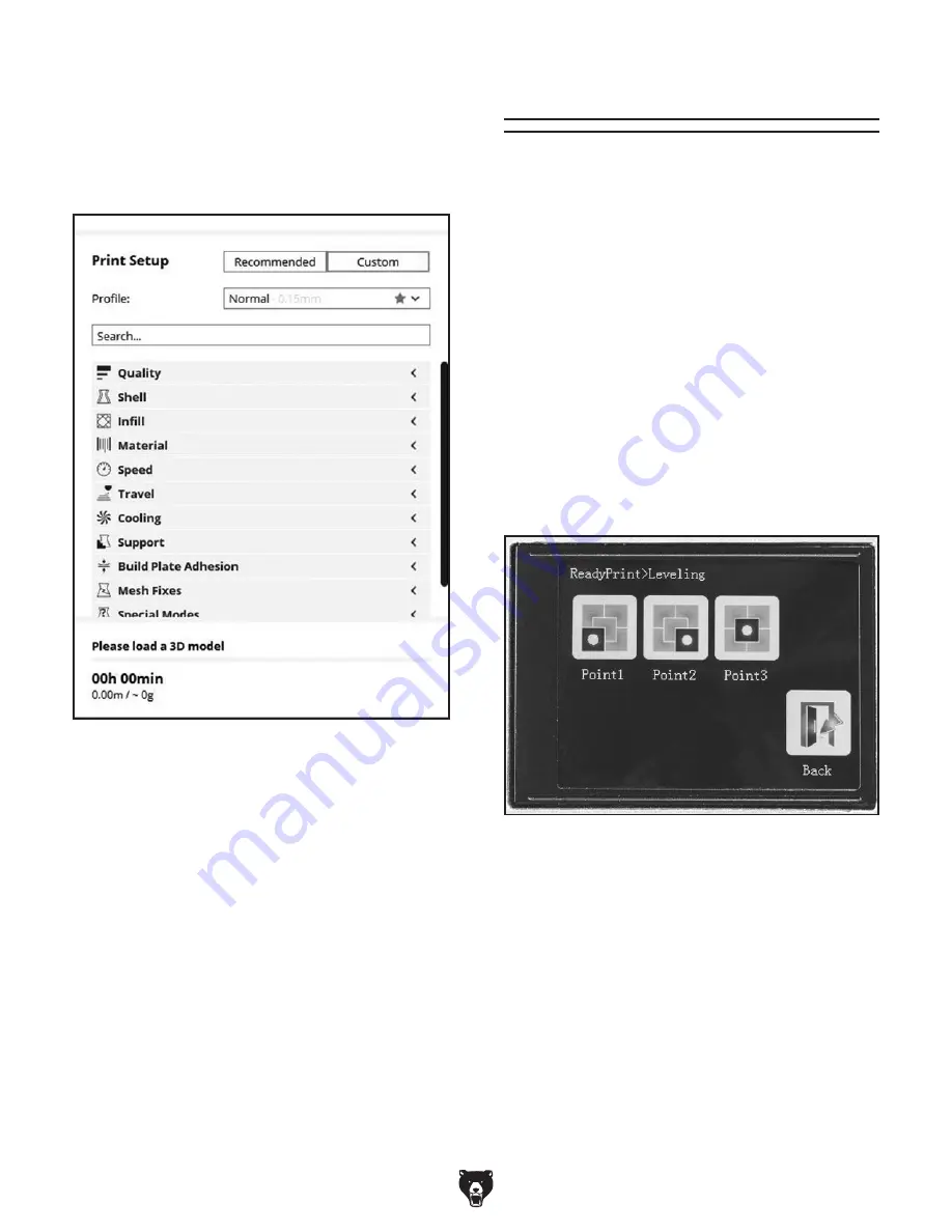
Figure 23. Custom print settings.

For  tasks  that  require  very  specific  settings  and 
resolving  print-quality  issues,  print  settings  can 
be  precisely  calibrated  through  the  custom  print 
setup pane. To open the custom pane, select the 
"Custom" button (see 

Figure 23).

Custom Print Setup

We  suggest  using  the  recommended  settings 
with  your  initial  prints  and  moving  to  the  custom 
settings when you have a specific need. Because 
the  range  of  options  is  so  wide,  giving  detailed 
instructions for the custom settings is beyond the 
scope of this manual. However, most settings are 
universal across 3D printers and slicer software. 
As you learn about 3D printing from other sourc-
es, you will find that the custom print setup has the 
options you need to make successful prints.

Leveling Build Plate

Tools Needed 

Qty

Sheet of Paper .................................................. 1

To level build plate with automatic function:

1.  Press "Leveling" icon on main menu.  Leveling 

menu will open (see 

Figure 24).

2.  Press  "Point1"  icon  (see  Figure  24).  X  and 

Y  axes  will  move  to  first  leveling  point  and 
Z-axis will raise to highest point.

The  build  plate  must  be  level  to  ensure  molten 
filament adheres properly and the nozzle does not 
snag  on  previous  layers.  In  addition  to  providing 
a  flat  surface,  leveling  the  build  plate  sets  the  Z 
height of your nozzle, which is essential for proper 
build plate adhesion.

Figure 24. Leveling menu.

Summary of Contents for G0922

Page 1: ...C WARNING NO PORTION OF THIS MANUAL MAY BE REPRODUCED IN ANY SHAPE OR FORM WITHOUT THE WRITTEN APPROVAL OF GRIZZLY INDUSTRIAL INC AI20900 PRINTED IN CHINA V1 08 20 MODEL G0922 ENCLOSED 3D PRINTER OWNE...

Page 2: ...g grinding tool integrity and the usage of personal protective equipment The manufacturer will not be held liable for injury or property damage from negligence improper training machine modifications...

Page 3: ...dels 19 Navigating Slicer Software 20 Leveling Build Plate 24 Preparing Build Plate 25 Preheating Nozzle 26 Printing 26 Changing Filament 28 Cleaning Build Plate 29 Moving Axes 29 SECTION 5 ACCESSORIE...

Page 4: ...de every effort to be exact with the instruc tions specifications drawings and photographs in this manual Sometimes we make mistakes but our policy of continuous improvement also means that sometimes...

Page 5: ...and locations of the controls and features shown below to better understand the instructions in this manual Print Head Nozzle Build Plate LCD Touch Screen SD Card Slot To reduce risk of machine damage...

Page 6: ...er to Main Menu on next page for more information E SD Card Slot Printer reads G code from SD card to print objects Figure 2 Components on back of machine G J K L M N H F Feeder Pulls filament from sp...

Page 7: ...o Moving Axes on Page 29 Printing Opens menu to choose file from SD card and start printing For more information refer to Printing on Page 26 Extrusion Opens menu to independently extrude filament For...

Page 8: ...an speed About Displays printer hardware and firmware information Continue Continues stopped print file from breakpoint For more information refer to Printing on Page 26 Filament Opens menu to load or...

Page 9: ...s axis points and commands Home Position A fixed point on the machine set with proximity switches It is the zero point for X Y and Z axes Hot End The heated portion of the extruder including heat sink...

Page 10: ...s Electrical Power Requirement 120V Single Phase 60 Hz Full Load Current Rating 6A Minimum Circuit Size 15A Connection Type Cord Plug w AC Adapter Power Cord Included Yes Power Cord Length 5 ft w Adap...

Page 11: ...mm s Number of Extruders 1 Nozzle Diameter 0 4 mm Filament Compatibility PLA Filament Diameter 1 75 mm Print File Type GCODE Software Information Included Software Grizzly Winware Supported OS Windows...

Page 12: ...d proof DANGEROUS ENVIRONMENTS Do not use machinery in areas that are wet cluttered or have poor lighting Operating machinery in these areas greatly increases the risk of accidents and injury MENTAL A...

Page 13: ...moving parts or flying debris Make sure they are properly installed undamaged and working correctly BEFORE operating machine FORCING MACHINERY Do not force machine It will do the job safer and better...

Page 14: ...build plate can burn immediately on con tact Do not touch nozzle or build plate when hot Allow components time to cool before performing maintenance MAINTENANCE SERVICE Always stop printer and wait f...

Page 15: ...ized circuit To reduce the risk of these hazards avoid over loading the machine during operation and make sure it is connected to a power supply circuit that meets the specified circuit requirements F...

Page 16: ...ord size gets longer and the gauge size gets smaller higher gauge numbers indicate smaller sizes Any extension cord used with this machine must be in good condition and contain a ground wire and match...

Page 17: ...tems out and inventory them If any non proprietary parts are missing e g a nut or a washer we will gladly replace them or for the sake of expediency replacements can be obtained at your local hardware...

Page 18: ...Wing Nuts M3 5 2 AD Zip Ties 4 AE Cord Clips 3 AF Insulated Spacers 2 AG Nozzle 1 AH Open End Wrench 10mm 1 AI Hex Wrenches 1 5 2 2 5 3mm 1 Ea AJ Bowden Tube Coupler 1 Figure 7 Parts and tools bag T...

Page 19: ...ess All icon to home all axes See Homing Axes on Page 30 Verify that the X Y and Z axis motors operate smoothly and that all axes move to machine zero build plate up and print head in rear right corne...

Page 20: ...izzly Industrial will not be held liable for accidents caused by lack of training Note We recommend backing up the installation files by copying them from the included SD card to a location on your co...

Page 21: ...chine damage and injury read this entire manual BEFORE using machine Preparing 3D Models Before an object can be printed a 3D model must be converted into G code by slicer software Most 3D models are...

Page 22: ...Page 22 Mirror Enters mirror model mode Refer to Manipulating Models on Page 22 Per Model Settings Opens menu for model spe cific settings when printing multiple models at once Build Area Frame Shows...

Page 23: ...bject viewer 4 Adjust model based on your printing needs Refer to Manipulating Model on Page 22 and Adjusting Print Settings on Page 23 for more detailed information 5 Select the Prepare button see Fi...

Page 24: ...0 The view can be rotated by right clicking the mouse and dragging it or panned by alt clicking the mouse usually the middle mouse button and dragging it Scrolling the mouse wheel zooms the view in an...

Page 25: ...can be modified for an expedited print time or to create an object that needs extra durability Enable Gradual This setting automatically deter mines the infill based on the model increasing the infill...

Page 26: ...s are universal across 3D printers and slicer software As you learn about 3D printing from other sourc es you will find that the custom print setup has the options you need to make successful prints L...

Page 27: ...plate 1 Open 2 clips at front of build platform and remove build plate see Figure 27 Preparing Build Plate Figure 26 Leveling menu 6 Repeat Steps 2 5 and check that nozzle height remains equal across...

Page 28: ...g the preheat temperature does not change the print temperature Once printing starts G code determines the print temperature based on filament settings in the slicer software Figure 29 Preheating temp...

Page 29: ...ite previous version of the file Pausing Print While paused the print head holds position and print settings can be changed Use pause for short breaks in printing or when changing set tings in the mid...

Page 30: ...Refer to Changing Filament More Opens menu with options to adjust air flow fan and print speed Changing Filament Use the Filament menu from machine settings to load or change filament If you are print...

Page 31: ...When tensioner is released filament should be pinched against hobbed gear see Figure 37 Hobbed Gear 1 Press Settings icon on main menu Setting menu will open 2 Press Filament icon on settings menu Fi...

Page 32: ...determined by axis limit switches 1 Press Extrusion icon on main menu Extrusion menu will open see Figure 41 2 Press extrusion increment icon to toggle between 1 5 and 10mm see Figure 29 3 Press In o...

Page 33: ...for 3D Printers T31836 Blue Filament for 3D Printers T31837 Yellow Filament for 3D Printers T31838 White Filament for 3D Printers T31839 Black Filament for 3D Printers 1 75mm diameter PLA filament for...

Page 34: ...y distribute grease refer to Moving Axes on Page 29 IMPORTANT Do NOT press or lift print head or move against rails Doing so could bend axis rails leading to poor print quality Lubricating X Y Axis Ra...

Page 35: ...e sprockets are aligned Page 42 2 Wire motor correctly Page 44 3 Tighten replace loose drive sprockets 4 Test repair replace 5 Test repair replace Machine has vibration or noisy operation 1 Cooling fa...

Page 36: ...at fault 1 Adjust temperature and restart preheating process Page 26 Lower temperature may require slower print speed 2 Unwind filament from spool until it is not tangled or overlapping 3 Replace fil...

Page 37: ...or leadscrew 1 Tension replace belt s ensure sprockets are aligned Page 42 2 Tighten replace loose drive sprockets Page 42 3 Clean and lubricate leadscrew Page 32 4 Test repair replace Occasional lay...

Page 38: ...gure 47 Breaking up residue inside nozzle using a guitar string A clogged nozzle can lead to significant printing issues Regularly performing brush and needle cleaning will help keep the Model G0922 p...

Page 39: ...Cold pull filament ends If removed end has carbonization and residue on it repeat Steps 3 6 If removed end is clean cold pull process is complete 3 Preheat nozzle refer to Preheating Nozzle on Page 2...

Page 40: ...ge 26 Before proceeding with the next step put on leather gloves to protect your hands while handling the hot nozzle and heating block 4 Hold heating block in place using crescent wrench while removin...

Page 41: ...le heating block is hot then cleaned with a blowtorch in the same manner as the nozzle refer to Step 5 11 Remove hot end from print head case by loosening 4 cap screws see Figure 56 Figure 53 Heat sin...

Page 42: ...d if threaded while cold DO NOT overtighten 22 Install air flow case to print head with 2 but ton head cap screws see Figure 50 on Page 38 23 Press down on tube coupler then insert Bowden tube into pr...

Page 43: ...ing block 4 Hold heating block in place using crescent wrench while removing nozzle with 10mm open end wrench see Figure 60 IMPORTANT Do not loosen remove or tighten nozzle unless heating block is hea...

Page 44: ...n on tube coupler and pulling firmly on Bowden tube see Figure 62 4 Cut small piece of sponge or ball up piece of tissue small enough to fit inside Bowden tube Aligning Axis Sprockets The X and Y axes...

Page 45: ...nect printer from computer Figure 67 Upgrade Firmware window Figure 66 Printer preferences window List of Printers Upgrade Firmware Button Upload Custom Firmware 3 Open Grizzly Winware software select...

Page 46: ...t at the time of printing but may not match your machine If you find this to be the case use the wiring diagram inside the motor junction box CAPACITORS INVERTERS Some capacitors and power inverters s...

Page 47: ...ont Rear Left E3 E2 E1 Z Y X X X Y Y Z Z AUX 1 AUX 1 HEAD1 brake FAN4 AUX 2 Servos1 Servos2 FAN3 FAN3 Laser TTL LEDS 5V D40 GND D4 D16 D17 RGB 24V HEATER1 HOT BED HEATER2 FAN1 FAN2 HEAD2 BED KCD4 16A...

Page 48: ...or OMRON SS 5GL Y motor X Fan2 Fan1 Heater1 Head1 Z1 X motor E motor OMRON SS 5GL OMRON SS 5GL Y DC BRUSHLESS FAN MODEL DF40B24H DC 24V 0 08A FAN DC24 0 15A C C CHA4024SX 20B FAN DC24 0 15A C C CHA402...

Page 49: ...CAL SAFETY ON PAGE 44 LED LED Filament Sensor Feeder E Axis LED Lights 12V 35W Interior Front Enclosure Panel Exterior Rear Enclosure Panel Additional Components Wiring Diagram Wiring Images Figure 68...

Page 50: ...2 Mfd Since 07 20 READ ELECTRICAL SAFETY ON PAGE 44 Wiring Images Cont Figure 72 LED light strip Figure 74 Motherboard Figure 70 Print head Figure 71 Touch screen display board Figure 73 Filament sens...

Page 51: ...82 60 90 91 108 81 108 75 9 9 9 106 110 107 102 109 10 10 11 12 12 12 13 14 15 16 17 18 19 20 21 21 22 23 23 24 25 26 27 28 29 30 31 31 31 31 31 31 31 31 31 32 33 32 33 32 34 34 34 34 35 35 36 36 37...

Page 52: ...R 81 P0922081 SPACER 3 X 7 X 20MM 27 P0922027 TUBE SUPPORT 82 P0922082 DRIVE SPROCKET 28 P0922028 FAN 4020 24V 83 P0922083 SPACER 8 X 14 X 8MM 29 P0922029 HEAT SINK 84 P0922084 SPACER 8 X 13 X 6MM 30...

Page 53: ...DESCRIPTION 201 P0922201 HEX WRENCH 1 5MM 207 P0922207 POWER ADAPTER AC TO DC 202 P0922202 HEX WRENCH 2MM 208 P0922208 POWER CORD 18G 3W 46 5 15P 203 P0922203 HEX WRENCH 2 5MM 209 P0922209 USB CABLE T...

Page 54: ...Full Load Current Rating 6A Build Volume 6 1 8 x 4 5 8 x 6 1 8 XY Precision 10 micron Z Precision 10 micron Nozzle Diameter 0 4mm Filament Diameter 1 75mm Filament PLA Weight 30 lbs Model G0922 3D Pri...

Page 55: ...for incidental contingent special or consequential damages arising from the use of our products The manufacturers reserve the right to change specifications at any time because they constantly strive...

Page 56: ......

Reviews: