

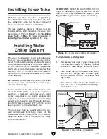


SIGNAL
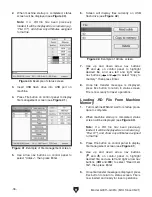
WATER IN
WATER OUT
AIR IN
Drain
TO INLET
Reservoir
TO WATER IN
Figure 16. Typical water chiller system setup.
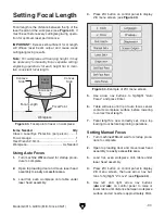
Figure 17. Water chiller connections.
Model G0911–G0914 (Mfd. Since 05/21)
-23-
Each CO
2
gas-filled laser tube is supported by
two soft-mount saddles and straps. Each tube has
four connection points: two for water inlet/outlet
hoses, and two for electrical connections.
On new machines, the laser tube(s)
must be
installed before additional setup procedures can
be completed. Perform
Steps 1–10 of Installing
Laser Tube on Page 68 before proceeding to
Installing Water Chiller System on this page.
Installing Laser Tube
Installing Water
Chiller System
The water chiller system should be located away
from any area where freezing temperatures may
occur. This includes locations where winter power
outages allow work areas to drop below freezing.
In cold environments, the low water temperature
alarm will activate when water temperature falls
below 50ºF (10ºC). To prevent water from freezing,
add 50/50 non-corrosive anti-freeze to the water
chiller reservoir.
IMPORTANT: Always use anti-freeze that is listed
as non-corrosive to prevent water hoses from pre-
maturely deteriorating.
In hot locations where ambient temperatures can
rise over 100ºF (37ºC), you may be required to
purchase a dedicated refrigeration-style water
cooler, have bags of ice readily available and
replaced, or incorporate additional water chilling
equipment in the same loop. The water tempera-
ture MUST be kept below 122ºF (50ºC) for proper
laser operation and maximum tube life.
The work area must be properly cleaned to pre-
vent contaminants from being drawn into the
water chiller and restricting airflow to the radiator.
Keep the water chiller a minimum of 12" away
from all obstructions.
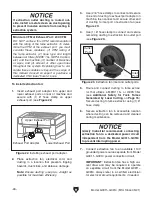
IMPORTANT: WATER IN and WATER OUT fit-
tings for the auxiliary systems are NOT revers-
ible. Correct hose orientation is required (see
Figure 16 for typical water chiller system setup).
To install water chiller system:
1. Remove any dust caps or plugs (if equipped)
from lines and fittings on auxiliary systems
connections, laser tube(s), and water chiller.
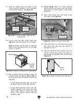
2. Install water tubing onto water chiller INLET
and OUTLET fittings, then connect signal
cord to ALARM OUTPUT receptacle (see
Figure 17).
Note: Water chiller for Model G0913 and
G0914 has one set of INLET/OUTLET fittings
for each laser tube.
110V Power
Connection
OUTLET
INLET
Drain
ALARM
OUTPUT
Reservoir
Water
Level
Gauge
Summary of Contents for G0911
Page 100: ......


