background image

MODEL G9860, G9860ZX, 

G9953ZX, & G9953ZXF

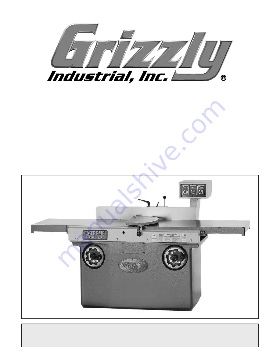
EXTREME SERIES JOINTER

OWNER'S MANUAL

(For models manufactured since 10/20)

COPYRIGHT © NOVEMBER, 2008 BY GRIZZLY INDUSTRIAL, INC., REVISED OCTOBER, 2020 (KS)

WARNING: NO PORTION OF THIS MANUAL MAY BE REPRODUCED IN ANY SHAPE

 OR FORM WITHOUT THE WRITTEN APPROVAL OF GRIZZLY INDUSTRIAL, INC.

 #TS11249  PRINTED IN TAIWAN

V6.10.20

Summary of Contents for EXTREME G9860

Page 1: ...For models manufactured since 10 20 COPYRIGHT NOVEMBER 2008 BY GRIZZLY INDUSTRIAL INC REVISED OCTOBER 2020 KS WARNING NO PORTION OF THIS MANUAL MAY BE REPRODUCED IN ANY SHAPE OR FORM WITHOUT THE WRIT...

Page 2: ...g grinding tool integrity and the usage of personal protective equipment The manufacturer will not be held liable for injury or property damage from negligence improper training machine modifications...

Page 3: ...ling Jointer 16 Adjusting Cutterhead Guard Tension 19 Setting Outfeed Table Height 19 Dust Collection 22 Test Run 22 Recommended Adjustments 23 SECTION 4 OPERATIONS 24 Basic Controls 24 Stock Inspecti...

Page 4: ...ANTY RETURNS 69 No list of safety guidelines can be complete Every shop environment is different Always consider safety first as it applies to your individual working conditions Use this and other mac...

Page 5: ...Phone 570 546 9663 Email techsupport grizzly com We want your feedback on this manual What did you like about it Where could it be improved Please take a few minutes to give us feedback Grizzly Docum...

Page 6: ...gure 1 Model G9860 G9860ZX identification A B C D E F G H I For Your Own Safety Read Instruction Manual Before Operating Jointer a Wear eye protection b Always keep cutterhead and drive guards in plac...

Page 7: ...d Speed 5900 RPM 5900 RPM 5000 RPM 5000 RPM Number of Cuts Min 23600 Effective 35400 Effective 30000 Effective 30000 Max Width of Cut 1113 16 1113 16 16 16 Max Depth of Cut 5 16 5 16 5 16 5 16 Table L...

Page 8: ...our workshop kid proof DANGEROUS ENVIRONMENTS Do not use machinery in areas that are wet cluttered or have poor lighting Operating machinery in these areas greatly increases the risk of accidents and...

Page 9: ...with moving parts or flying debris Make sure they are properly installed undamaged and working correctly BEFORE operating machine FORCING MACHINERY Do not force machine It will do the job safer and be...

Page 10: ...can increase risk of kickback It also requires more cutting force which produces chat ter or excessive chip out Always joint or surface plane WITH the grain CUTTING LIMITATIONS Cutting workpieces tha...

Page 11: ...undersized circuit To reduce the risk of these hazards avoid over loading the machine during operation and make sure it is connected to a power supply circuit that meets the specified circuit requirem...

Page 12: ...unted and secured conduit A disconnecting means such as a locking switch see following figure must be provided to allow the machine to be disconnected isolated from the power supply when required This...

Page 13: ...an extension cord only use it if absolutely necessary and only on a temporary basis Extension cords cause voltage drop which can damage electrical components and shorten motor life Voltage drop increa...

Page 14: ...ce the motor junction box cover and access panel before connecting the jointer to power 4 5 6 7 8 9 1 2 3 Ground Figure 8 Illustration of motor wired for 440V operation Terminal Jumper 3 Use a small f...

Page 15: ...oor Mounting Hardware As Needed Cleaning Solvent Shop Rags As Needed Precision Straightedge 6 1 Phillips Screwdriver 2 1 Hex Wrench 10mm 1 Wrench 18mm 1 Needed for Setup Your machine was carefully pac...

Page 16: ...x 14 x 2mm 10 Flat Head Torx Screws T 20 M6 1 x 15 30 The unpainted surfaces are coated with a waxy oil to prevent corrosion during shipment Remove this protective coating with a solvent cleaner or de...

Page 17: ...machine to the floor Because this is an optional step and floor materials may vary floor mounting hardware is not included Generally you can either bolt your machine to the floor or mount it on machi...

Page 18: ...es of the shipping crate then place the small items aside in a safe location 3 Remove the four pre installed cap screws from the back of the jointer then with assis tance secure the pedestal to the jo...

Page 19: ...force the table handwheels if you feel resistance Check the positions of the stop bolts or for obstructions 8 Loosen the jam nut see Figure 17 on the infeed stop bolt then unthread the stop bolt until...

Page 20: ...istance place the fence assembly onto the fence base support Figure 21 Fence assembly installed Fence Mounting Cap Screws 3 of 6 Fence Assembly Fence Base Support 3 Secure the fence assembly with the...

Page 21: ...ace 5 Re test and if necessary repeat Step 4 until the guard has the correct tension Setting Outfeed Table Height The outfeed table height MUST be even with the knives cutters when they are at top dea...

Page 22: ...it out and rotate it 1 2 turn Stop Plate Indent Lock Pin Knurled Knob Fence Support Figure 24 Cutterhead lock pin engaged 3 Place the straightedge on the center of the outfeed table and over the cutt...

Page 23: ...hes the straightedge when at TDC then tighten the table lock The outfeed table MUST be even with the cutter edges to reduce the risk of kickback and to help ensure good cutting results Tip Some advanc...

Page 24: ...liar with the various functions and safety features on this machine Failure to follow this warning could result in serious personal injury or even death Test Run Once the assembly is complete test run...

Page 25: ...een performed at the factory and no further setup is required to operate your machine However because of the many variables involved with shipping we recommend that you at least verify the following a...

Page 26: ...jewelry could get caught in machinery and cause serious personal injury Keep these items away from moving parts at all times to reduce this risk Basic Controls Refer to Figures 29 33 and the followin...

Page 27: ...mbly in place Fence Tilt Handle Tilts the fence when the tilt lock is loose Fence Tilt Lock Locks the fence tilt angle in place when tightened Fence Stops Provide positive stops for the fence at 90 an...

Page 28: ...roduce poor results Remove foreign objects from the workpiece Make sure that any stock you process with the jointer is clean and free of dirt nails staples tiny rocks or any other foreign objects that...

Page 29: ...of the workpiece is sur face planed flat with a thickness planer see Figure 37 Previously Surface Planed Face Figure 37 Surface planing on a thickness planer 3 Edge Joint on the Jointer The concave ed...

Page 30: ...of cut for your operation and the fence to 90 Note We suggest a 1 32 depth of cut for sur face planing and a more shallow depth for hardwood species or for wide stock 5 If your workpiece is cupped or...

Page 31: ...ur operation and the fence to 90 Note We suggest 1 16 1 8 depth of cut for edge jointing and a more shallow depth for hardwood species or for wide stock 5 If your workpiece is cupped or warped place i...

Page 32: ...Set the depth of cut for your operation and the fence to the required angle Note We suggest 1 16 1 8 depth of cut for bevel cutting and a more shallow depth for hardwood species or for wide stock 5 If...

Page 33: ...knife holders and one set of disposable double edge HSS Dispoz A Blade knives that are cor rectly sized for your machine All that is required for future knife changes is the purchase of inex pensive...

Page 34: ...ar T20451 T20452 T20502 T20503 T20456 G0862 3 HP Portable Cyclone Dust Collector The capstone of our new line of affordable high quality cyclones the G0862 features a 3 HP motor a whopping 1941 CFM of...

Page 35: ...nside the cabinet and off the motor Lubricate the pivot points of the fence assem bly Page 34 Lubricate the cutterhead bearing blocks Page 34 Every 160 Hours of Operation Lubricate the table elevation...

Page 36: ...n coat of lubricant to these parts Lubrication Other than lubrication points covered in this sec tion all other bearings are internally lubricated and sealed at the factory Simply leave them alone unl...

Page 37: ...ssembly until there is the proper tension on the V belts Note The V belts are properly tensioned when there is approximately 3 4 of deflection between the pulleys when moderate pres sure is applied wi...

Page 38: ...eed too fast 2 Workpiece material not suitable for machine 3 Dust collection ducting problem 4 V belt s slipping 5 Motor wired incorrectly 6 Plug receptacle at fault 7 Pulley sprocket slipping on shaf...

Page 39: ...rain Page 26 2 Replace rotate knives inserts Pages 38 39 3 Reduce feed rate 4 Reduce the depth of cut 5 Check dust collection for proper operation clear blockages reconfigure ducting system Fuzzy grai...

Page 40: ...crew and the surrounding area 4 Remove the Torx screw and the insert then clean all dust and debris from both parts and the pocket they were removed from Note Proper cleaning of the insert Torx screw...

Page 41: ...alled correctly and at the same height as the other inserts If the insert is raised above the correct height remove it and repeat the above procedure until it is properly installed Air Pressure Torque...

Page 42: ...ves when handling these cut ters to avoid personal injury 3 Remove the cutterhead guard fence assem bly and rear motor access cover to access the cutterhead pulley 4 Use the cutterhead pulley to rotat...

Page 43: ...rd 6 Carefully remove the knife and gib 7 If the knife is dull or damaged replace it with a new one 8 Clean the knife gib and inside the cutterhead slot to remove all the pitch or sawdust Coat the kni...

Page 44: ...setting Figure 65 Setting the fence to 90 cutterhead guard moved away for clarity 4 Adjust the 45 set screw until it just touches the tilting arm then re tighten the jam nut Figure 66 Setting the fen...

Page 45: ...POWER 2 Loosen fence tilt lock and 45 stop jam nut then back off stop bolt see Figure 68 3 Place bevel square set at 135 flat against outfeed table near cutterhead as shown in Figure 66 on Page 42 ad...

Page 46: ...head and 2 adjust the infeed table parallel to the outfeed table Note If your jointer uses a knife style cutterhead you will also have to adjust the knives as the last procedure to bring the outfeed t...

Page 47: ...table surface is not at the right height use the handwheel to bring the table to the correct height above the cutterhead then tighten the table lock to secure the set ting 6 To check the outfeed tabl...

Page 48: ...the back of the table to the correct height above the cutterhead body then repeat Step 9 Continue this process until the table height is correct and the same from front to back 11 When the outfeed ta...

Page 49: ...bolts on the back side of the infeed table remove the back table cover 5 Use the same process you performed in Step 9 on Page 46 to raise or lower the left or right end of the infeed table to elimina...

Page 50: ...current at the time of printing but may not match your machine If you find this to be the case use the wiring diagram inside the motor junction box CAPACITORS INVERTERS Some capacitors and power inver...

Page 51: ...220V 2T1 4T2 6T3 5 4 NO X1 X2 1 2 NC X1 X2 POWER STOP ON LAMP Ground Start Capacitor 400MFD 250VAC Hot Hot Ground 220VAC NEMA 6 20 Plug As Recommended 220 VAC G Ground Ground Motor 1 2 3 4 Electrical...

Page 52: ...ay RHU 80A2 TECO Contactor CU 27 220V T1 T2 T3 3 4 NO X1 X2 1 2 NC X1 X2 POWER STOP ON LAMP Ground Ground Ground Motor NEMA L6 30 L6 30 PLUG as recommended G X Y Run Capacitor 30MFD 350VAC Start Capac...

Page 53: ...97 NO 98 NC 95 NC 96 NC LOAD 15 TECO O L Relay RHU 10 TECO Contactor CU 18 220V 2T1 4T2 6T3 3 4 NO X1 X2 1 2 NC X1 X2 POWER STOP ON LAMP Ground Ground Motor NC NO COM 1 2 3 4 5 Electrical Pedestal 1 C...

Page 54: ...As Recommended 4 2T1 6T3 14NO 4T2 1L1 5L3 13NO 3L2 A1 A2 97 NO 98 NC 95 NC 96 NC LOAD 7 2 TECO O L Relay RHU 10 TECO Contactor CU 18 440V 2T1 4T2 6T3 3 4 NO X1 X2 1 2 NC X1 X2 POWER STOP ON LAMP Grou...

Page 55: ...5 P9860005 OUTFEED TABLE SUPPORT 27 P9860027 CAP SCREW M10 1 5 X 25 9 P9860009 TABLE HEIGHT SPINDLE 30 P9860030 FRONT CABINET ACCESS COVER 10 P9860010 OUTFEED TABLE LIFTING ARM 31 P9860031 HEX BOLT M6...

Page 56: ...head Motor 801 802 803 101A 102 103 104 105 106 107 108 109 110 111 112 113 114 115 116 117 118 119 120 121 122 701 701 1 701 2 701 3 702 703 704 705 706 707 708 709 710 711 104 110 101 1 Spiral Cutte...

Page 57: ...1 75 X 40 116 P9860116 BRACKET 710 P9860710 MOTOR MOUNT PLATE 117 P9860117 FLAT WASHER 10MM 711V2 P9860711V2 V BELT A47 118 P9860118 HEX BOLT M10 1 5 X 16 G9860ZX Cutterhead Motor Parts List REF PART...

Page 58: ...treme Series Jointer Mfd Since 10 20 G9860 ZX Fence 2 18 19 20 21 22 201 202 203 204 205 206 207 208 209 210 211 212 213 214 215 216 217 218 219 220 221 601 602 603 604 605 606 607 222 18 1 216 Model...

Page 59: ...60022 CAP SCREW M12 1 75 X 30 218 P9860218 FLAT WASHER 10MM 201 P9860201 FENCE BASE 219 P9860219 CAP SCREW M10 1 5 X 25 202 P9860202 PIVOT BRACKET 220 P9860220 FENCE ADJUSTMENT HANDLE 203 P9860203 CON...

Page 60: ...T WASHER 1 2 25 P9860025 HEX BOLT M8 1 25 X 16 314 P9860314 FLAT WASHER 3 8 29 P9860029 KNOB M10 1 5 X 30 315 P9860315 HEX NUT M12 1 75 301 P9860301 OUTFEED TABLE 316 P9860316 TABLE PIVOT ROD SHORT 30...

Page 61: ...P9860515 SET SCREW M4 7 X 10 504 P9860504 SLEEVE 516 P9860516 GREASE FITTING 505 P9860505 LIFT ROD 517 P9860517 KEY 5 X 5 X 15 506 P9860506 GEAR SHAFT 518 P9860518 LOCK WASHER 8MM 507 P9860507 LIFT CO...

Page 62: ...53ZX024 STOP BUTTON 5 P9953ZX005 OUTFEED TABLE LIFTING ARM 25 P9953ZX025 POWER LAMP 6V2 P9953ZX006V2 DUST HOOD 5 V2 10 20 26 P9953ZX026 PHLP HD SCR M6 1 X 12 8 P9953ZX008 TABLE HEIGHT SPINDLE 27 P9953...

Page 63: ...9953ZX120 CUTTERHEAD REAR COVER 105 P9953ZX105 BALL BEARING 6208ZZ 121 P9953ZX121 PHLP HD SCR M4 7 X 15 106 P9953ZX106 BEARING END CAP 122 P9953ZX122 STAR KNOB 107 P9953ZX107 BRAKE NUT M30 1 5 123 P99...

Page 64: ...ce 10 20 G9953ZX ZXF Fence 201 202 203 204 205 206 207 208 209 210 211 212 213 214 215 216 217 218 219 220 221 222 223 224 225 228 229 230 231 232 233 234 235 236 237 238 239 240 241 235 226 226 218 2...

Page 65: ...P9953ZX233 PIVOT PIN LEFT 210 P9953ZX210 CAP SCREW M6 1 X 10 234 P9953ZX234 FENCE ROD 211 P9953ZX211 GEAR SHAFT 235 P9953ZX235 PIVOT ARM 212 P9953ZX212 HANDWHEEL 236 P9953ZX236 FENCE ANGLE SEAT 213 P9...

Page 66: ...d Since 10 20 G9953ZX ZXF Table 7 9 10 11 12 18 301 302 303 304 305 306 307 308 309 310 311 312 313 314 315 316 401 402 403 404 405 801 802 803 804 805 806 807 11 12 41 43 44 45 46 47 48 49 50 51 52 5...

Page 67: ...6 BRAKE BRACKET 315 P9953ZX315 CAP SCREW M10 1 5 X 45 47 P9953ZX047 BRAKE PAD 316 P9953ZX316 J ROD SHORT 48 P9953ZX048 PHLP HD SCR 10 24 X 1 2 317 P9953ZX317 TABLE PIVOT ROD SHORT 49 P9953ZX049 FLAT W...

Page 68: ...SET SCREW M4 7 X 10 504 P9953ZX504 SLEEVE 516 P9953ZX516 GREASE FITTING 505 P9953ZX505 LIFT ROD 517 P9953ZX517 KEY 5 X 5 X 15 506 P9953ZX506 GEAR SHAFT 518 P9953ZX518 LOCK WASHER 8MM 507 P9953ZX507 LI...

Page 69: ...4 708 P9953ZX708 KEY 7 X 7 X 65 701 5 P9953ZX701 5 R CAP 30M 350V 3 X 2 709 P9953ZX709 SET SCREW M8 1 25 X 20 702 P9953ZX702 MOTOR PULLEY 710 P9953ZX710 MOTOR MOUNT PLATE 703 P9953ZX703 LOCK WASHER 10...

Page 70: ...0ZX 719 P9860ZX719 MODEL NO LABEL G9860ZX 714 P9953ZX714 MACHINE ID LABEL G9953ZX 719 P9953ZX719 MODEL NO LABEL G9953ZX 714 P9953ZXF714 MACHINE ID LABEL G9953ZXF 719 P9953ZXF719 MODEL NO LABEL G9953ZX...

Page 71: ...for incidental contingent special or consequential damages arising from the use of our products The manufacturers reserve the right to change specifications at any time because they constantly strive...

Page 72: ......

Reviews: