- 1 -
H G 1 0 9 5 E
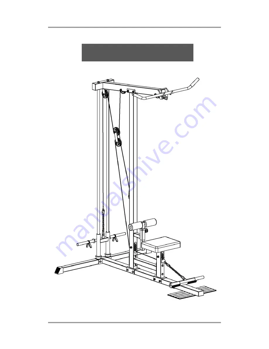
A S S E M B L Y I N S T R U C T I O N S
Page 1: ... 1 H G 1 0 9 5 E A S S E M B L Y I N S T R U C T I O N S ...
Page 2: ... 2 PRODUCT EXPLOSIVE DRAWING ...
Page 3: ... PULL BOW 1 L LAP BOW 1 M WEIGHT PLATE SLEEVE 1 N SHORT JOINT PLATE 1 O NYLON BUSH 4 P SEAT PAD 1 Q JOINT TUBE 1 R PULLEY SUPPORT 2 1 PLASTIC END CAP 2 2 FOAM ROLLER 2 3 PLASTIC BUSH 8 4 RUBBER DONUT 2 5 BOLT M10 20 WASHER 2 6 BOLT M10 50 TWO WASHER NUT 3 7 BOLT M10 70 TWO WASHER NUT 8 8 SPRING CLIP 2 9 BOLT M10 85 TWO WASHER NUT 1 10 BOLT M10 90 TWO WASHER NUT 8 11 BIG WASHER 2 12 BOLT M12 85 WAS...
Page 4: ...se B with two bolts M10 90 four washers two nuts 10 7 Attach the top cross beam F to the main vertical beam D with two bolts M10 70 four washers two nuts 7 8 Attach the guide rod G to the top cross beam F with two bolts M12 85 two washers 12 9 Attach the seat pad support I and joint tube Q to the main base B and the main vertical beam D with the short joint plate N two bolts M10 90 four washers tw...
Page 5: ... to avoid damages of the cable Through the cable under pulley 3 on pulley support R up and round pulley 4 on top cross beam F finally attach the cable to weight plate sleeve M with hooks and short chain 2 Through the end with no ball of the short cable under pulley 5 on seat pad support I then under pulley 6 on main vertical beam D up and round pulley 7 on pulley support R finally attach the cable...