background image

481153 • IGX, Rev. 5, September 2019 

Copyright 2019 © Greenheck Fan Corporation

48

As a result of our commitment to continuous improvement, Greenheck reserves the right to change specifications 
without notice.

Product warranties can be found online at Greenheck.com, either on the specific product page or in the literature 
section of the website at Greenheck.com/Resources/Library/Literature.

®

Phone: 715.359.6171 • Fax: 715.355.2399 • Parts: 800.355.5354 • E-mail: [email protected] • Website: www.greenheck.com

Our Commitment

Greenheck's Model IGX and Model IG-HV and IGX-HV 
catalogs provide additional information describing the 
equipment, fan performance, available accessories, and 
specification data.

AMCA Publication 410-96, Safety Practices for Users and 
Installers of Industrial and Commercial Fans, provides 
additional safety information. This publication can be obtained 
from AMCA International, Inc. at www.amca.org.

Date ___________________Time _____________ AM/PM

Notes: ___________________________________________

_________________________________________________

_________________________________________________

_________________________________________________

_________________________________________________

Reference

Maintenance Log

Summary of Contents for IG-HV Series

Page 1: ...jects 3 Motor must be securely and adequately grounded 4 Do not spin fan wheel faster than the maximum cataloged fan rpm Adjustments to fan speed significantly affects motor load If the fan RPM is changed the motor current should be checked to make sure it is not exceeding the motor nameplate amps 5 Do not allow the power cable to kink or come in contact with oil grease hot surfaces or chemicals Re...

Page 2: ...Control w micro 25 Duct Pressure Control 25 Carbon Dioxide CO2 Sensor 25 Duct Mounted Smoke Detector 25 Supply Fan Fan Identification 26 Pre Start Checks 27 Start Up 28 Start Up Indirect Gas Fired Heating Optional Features Variable Air Volume 29 Recirculation Operation 30 Start Up Optional Features Evaporative Cooling Module 31 Other Building Freeze Protection 32 Microprocessor Controls 32 PDX Coo...

Page 3: ...ion Remove any accumulations of dirt water ice or snow and wipe dry before moving to indoor storage To avoid condensation allow cold parts to reach room temperature Leave coverings loose to permit air circulation and to allow for periodic inspection The unit should be stored at least 3 in 89 mm off the floor Clearance should be provided to permit air circulation and space for inspection Outdoor The...

Page 4: ...l IOMs for Reference Electronic Modulation Single Furnace Unit 4 1 uses modulating valve and furnace controller High turndown uses a 4 1 modulating valve with a proprietary manifold and furnace controller Two Furnace Unit 8 1 uses one 4 1 modulating furnace with furnace controller and one 2 stage furnace 4 1 uses two 4 1 modulating furnaces controlled in parallel High turndown furnaces in a series...

Page 5: ... equipped with evaporative cooling module 61 in 155 cm when equipped with evaporative cooling module over 4800 cfm Service Clearances Service clearances are factory recommendations for ease of servicing All deviations must still adhere to clearance to combustibles requirements All deviations from the service clearance recommendations are at the discretion of the end user as this may impede compone...

Page 6: ...ning ductwork Installation Duct Sizes Down Discharge End Discharge Housing Furnace Size MBH H W H W 12 100 25 23 15 31 150 25 23 21 31 200 25 23 27 31 250 25 23 32 31 22 150 26 25 21 31 200 26 25 27 31 250 26 25 32 31 300 26 25 38 31 350 26 34 39 41 4 400 26 34 39 41 4 500 26 25 32 31 600 26 25 38 31 32 250 26 34 30 41 300 26 34 30 41 350 26 34 39 41 400 26 34 39 41 500 26 34 30 41 600 26 34 30 41...

Page 7: ...Manual for proper duct sizes 5 Seal Wall Opening Sealant must be applied around the perimeter of the weatherhood to prevent water penetration and drafts into the building Indoor Unit Mounting Floor Mounted 1 Install Unit Use a crane and a set of spreader bars hooked to the factory lifting lugs to lift and locate the unit in place The use of all lifting lugs and a set of spreader bars is mandatory ...

Page 8: ...5 29 38 33 85 4 4 4 4 4 6 200 5 67 9 67 24 97 31 9 6 6 6 6 6 8 250 5 67 9 67 24 97 31 9 6 6 6 6 6 8 300 5 67 9 67 24 97 31 9 6 6 6 6 6 8 350 5 67 9 67 19 01 25 94 6 6 6 6 6 8 400 5 67 9 67 19 01 25 94 6 6 6 6 6 8 500 5 67 9 67 24 97 31 9 6 6 6 6 6 8 600 5 67 9 67 24 97 31 9 6 6 6 6 6 8 32 250 5 67 9 67 28 32 35 64 6 6 6 6 6 8 300 5 67 9 67 28 32 35 64 6 6 6 6 6 8 500 5 96 9 71 28 31 35 24 6 6 6 6 ...

Page 9: ...31 08 25 55 4 4 4 4 4 6 200 5 67 9 67 20 21 27 14 6 6 6 6 6 8 250 5 67 9 67 24 97 31 9 6 6 6 6 6 8 300 5 67 9 67 24 97 31 9 6 6 6 6 6 8 350 5 67 9 67 19 01 25 94 6 6 6 6 6 8 400 5 67 9 67 19 01 25 94 6 6 6 6 6 8 500 5 67 9 67 24 97 31 9 6 6 6 6 6 8 600 5 67 9 67 24 97 31 9 6 6 6 6 6 8 32 250 5 67 9 67 28 32 35 64 6 6 6 6 6 8 300 5 67 9 67 28 32 35 64 6 6 6 6 6 8 500 5 96 9 71 28 31 35 24 6 6 6 6 6...

Page 10: ... Support 2 Install Ductwork Follow good duct practices for all ductwork Install ductwork in accordance with SMACNA and AMCA guidelines NFPA 96 and local codes Reference Installation Duct Sizes section in this Installation Operation and Maintenance Manual for proper duct sizes The use of a duct adapter is recommended on a downblast DB arrangement to align the ductwork with the supply unit The duct ...

Page 11: ... that the unit fastening methods are sufficient to account for the weight and size of these additional modules 6 Seal Seam s Using an appropriate sealant seal the seam s between each shipped loose module and the weatherhood 4 Install Unit Use a crane and a set of spreader bars hooked to the factory lifting lugs to lift and position the unit on the curb equipment support s The use of all lifting lug...

Page 12: ...iate methods field provided The installer is responsible for determining appropriate support and fastening methods to ensure compliance with all applicable codes Exhaust Supply 1 inch Inside Flange Combination Extension Installation Outdoor Unit Mounting Combination Curb 1 Install Curb and Equipment Leg Support s Position curb and equipment leg support s on the roof reference the unit submittal for...

Page 13: ...ting Combination Curb continued 6 Install Exhaust Fan Options Install hinges an optional hinge kit is available from manufacturer with restraining cables and optional grease trap with drain connection 7 Install Supply Unit Use a crane and a set of spreader bars hooked to the factory lifting lugs to lift and position the unit on the curb extension and equipment support s The use of all lifting lugs...

Page 14: ...unting Evaporative Cooling Module section in this IOM for more information The installer is responsible for ensuring that the unit fastening methods are sufficient to account for the weight and size of these additional modules 9 Seal Seam s Using an appropriate sealant seal the seam s between each shipped loose module and weatherhood Combination Curb continued 10 Install Stack optional Clearance ma...

Page 15: ...ack Install an exhaust stack as needed to the exhaust connection on the unit Install a vent terminator on the exhaust pipe Exhaust transition and vent termination must be purchased from the factory for proper operation Exhaust pipe is by others Rail 1 Install Rails The rails must be located around the perimeter of the base unit on all four sides This is required to ensure proper unit support 2 Ins...

Page 16: ...to the base unit along the top and down both sides Fasten at the top through the cover flanges To fasten the sides the media may need to be removed To remove the media first remove the access panel on the evaporative module and disconnect the evaporative pump s The media will now slide out With the media removed you can access the side fastening points inside the evaporative cooling module With all ...

Page 17: ...ad and understand the following instructions and wiring diagrams Complete wiring diagrams are attached on the inside of the control center door s All wiring must be done in accordance with the latest edition of the National Electrical Code NFPA 70 and any local codes that may apply In Canada wiring must be done in accordance with the Canadian Electrical Code The equipment must be properly grounded...

Page 18: ...or the cooling system When a call for cooling has been signaled the cooling relay closes a dry NO contact rated for 8 amps and 250 VAC Carbon Dioxide CO2 Sensor Depending on the application recirculating units may have been provided with a wall mounted CO2 sensor The CO2 sensor is intended to prevent the build up of CO2 in the space It must be wired as indicated on the unit wiring diagram to comma...

Page 19: ...iled unit operation Control Voltage Manufacturer s standard control voltage is 24 VAC Control wire resistance must not exceed 0 75 ohms approximately 285 feet total 86 9 m length for 14 gauge wire 455 feet 138 7 m total length for 12 gauge wire If the resistance exceeds 0 75 ohms an industrial style relay must be wired in place of the remote switch The relay must be rated for at least 5 amps and h...

Page 20: ...ass Consult authorities having jurisdiction before installations are made All piping must be clean and free of any foreign matter Foreign material entering the gas train can damage the valves regulators and burner Do not connect the unit to gas types other than what is specified and do not connect the unit to gas pressures that are outside of the pressure range shown on the label When connecting th...

Page 21: ...r line from freezing If they cannot be installed below the roof an alternative method must be used to protect the lines from freezing CAUTION Provisions must be taken to prevent damage to the evaporative cooling section during freezing conditions The sump drain lines and supply lines must be drained prior to freezing conditions or an alternate method must be used to protect the lines and media Sin...

Page 22: ... the 3 4 in normally open solenoid Valve C between the sump drain connection and the drain line A trap must be provided for proper unit drainage Single Pass Connect an unobstructed drain line to the sump drain and overflow connections A trap must be provided for proper unit drainage 6 in min 0 254 cm sec 6 in min 0 254 cm sec Drain Trap Optional Evaporative Cooling Module continued 3 Check Adjust W...

Page 23: ...can be left as is If a hot gas bypass kit was provided by others refer to the manufacturer s instructions Distributor Access Panel Retainer Ring Nozzle Distributor General Installation Expansion Valve by others Liquid Line Thermal Nozzle Suction Header Coil Distributor Equalizer Line Suction Line Remote Sensing Bulb Straps Suction Connection 5 Mount the TXV Sensing Bulb by others Mount the TXV sen...

Page 24: ...ystem Coils are generally plumbed with the supply connection located on the bottom of the leaving air side of the coil and the return connection at the top of the entering air side of the coil This arrangement provides a counter flow heat exchanger and positive coil drainage Return Connection Cold Supply Connection Entering Air Leaving Air Guidelines for the installation of chilled water cooling co...

Page 25: ...shipped loose Duct Pressure Control The optional microprocessor controller can be selected to modulate the supply fan based upon a comparison of the duct static pressure set point to the actual duct static pressure level reported from the sensor The factory supplied sensor will ship loose for field mounting and wiring Further component identification and terminal designation can be found by referenc...

Page 26: ... Models VSU or TSU units use two forward curved fans with a common shaft Backward Curved Plenum Fans Backward curved plenum fans are single width single inlet fans The impellers are unhoused with blades that curve away from the direction of rotation These fans throw the air radially outward 90 F from the inlet direction pressurizing the fan cabinet These fans are direct driven with the impeller mo...

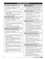
Page 27: ...h a Variable Frequency Drive VFD due to the direct drive arrangement on the supply fan Before proceeding further identify if this is a constant volume or Variable Air Volume VAV unit Reference the Start Up Indirect gas Fired Heating Optional Features Variable Air Volume section in this Installation Operation and Maintenance Manual for further information 1 Check Electrical Connections Tug test all...

Page 28: ...s Motor amps can be reduced by lowering the fan RPM or increasing system static pressure Additional starters and overloads may be provided in the make up air control center for optional external exhaust fans Exhaust fan motor voltage must match unit nameplate voltage Exhaust fan overloads must be set to exhaust fan motor Full Load Amps FLA Reference the exhaust fan manual for additional informatio...

Page 29: ...the factory and rarely need any adjustment during installation and start up For some applications the drive may be located in the building or in the unit The VAV option is recommended when a building s exhaust volume may vary This option enables the make up air volume to track the exhaust volume providing only the amount of make up air required Control strategies include 2 speed and modulating opt...

Page 30: ...mmissioning test the recirculation control system 2 Position Option A 2 position spring return actuator is used to control the return air amounts The damper moves from open to closed If power is cut to the unit the outdoor air damper will fail closed Turn the recirculating switch on the remote control panel to each position and confirm that the return air damper adjusts accordingly The damper actua...

Page 31: ...te flow is not achieved If too much water is flowing to the media the flow can be adjusted using the manual ball valve If flow adjustments are made verify that sufficient water is still being supplied to the media to keep the entire pad wet during normal operation Excessive water flow can result in water carryover problems Insufficient water flow can result in mineral build up Bleed Off Valve Overflo...

Page 32: ... clean and in good condition The adjusting screw is located on the top of the switch Setscrew on front of switch must be manually adjusted after the system is in operation Negative pressure connection is toward the front or top of the switch Senses pressure on the fan side of filters Positive pressure connection is toward the back or bottom of the switch Senses pressure at the inlet side of filter...

Page 33: ...passes to and energizes cooling relay RC Cooling sequence begins Cooling Sequence Recirculating Pump Evaporative Cooling Whenever the cooling relay RC is energized power passes through the normally open cooling relay to the evaporative cooling pump P1 The evaporative cooling pump s are energized and cooling begins Cooling Sequence Auto Drain and Fill Evaporative Cooling Power passes to the evapora...

Page 34: ... to the speed commanded by the potentiometer External Signal VFD Control When the supply fan relay RF is energized the normally open supply fan relay RF contacts are closed This creates a run command for the VFD The run command allows the VFD to pass power to the supply fan M1 The supply fan M1 will operate at the speed commanded by the external signal provided by others The external signal provid...

Page 35: ...t Setback Schedule The night setback schedule is established within the programmable thermostat on the remote panel The schedule must be set for the occupied and unoccupied hours of the controlled space Night Setback Fan Control During occupied hours the fan sequence of operation is the same as that described in the Supply Fan section During unoccupied hours the fan is turned off If there is a cal...

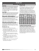
Page 36: ...nded Bearing Lubrication Schedule in months Fan RPM Bearing Bore Size inches 1 2 1 11 8 11 2 15 8 17 8 115 16 23 16 27 16 3 250 6 6 6 6 6 500 6 6 6 5 4 750 6 5 4 3 3 1000 5 3 2 1 1 1250 5 3 2 1 1 1500 5 2 1 1 0 5 2000 5 1 1 0 5 0 25 Suggested initial greasing interval is based on 12 hour per day operation and 150 F 48 9ºC maximum housing temperature For continuous 24 hour operation decrease greasi...

Page 37: ...eaving Air Entering Air 45º 15º Media Orientation Motors Motor maintenance is generally limited to cleaning and lubrication where applicable Limit cleaning to exterior surfaces only Removing dust and grease build up on the motor assures proper motor cooling Grease motors supplied with grease fittings in accordance with the manufacturer s recommendations Do not allow water or solvents to enter the m...

Page 38: ...the other header 5 Turn on blower for 30 minutes Place mirror at discharge If the mirror fogs up repeat procedure until no fog appears on the mirror 6 After drying the coil wait a few minutes then repeat Step 5 7 Leave drains open and do not install plugs until beginning of cooling season Maintenance Seasonal Heating Cooling Flushing Coils Manufacturer recommends the use of inhibited glycol such a...

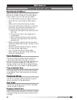
Page 39: ...stall manifold and burner assembly reconnect wire leads and gas supply piping Turn on the electrical power and gas supply Follow the start up procedure to light the burners and verify proper operation Heat Exchanger The heat exchanger should be checked annually for cracks and discoloration of the tubes If a crack is detected the heat exchanger should be replaced before the unit is put back into op...

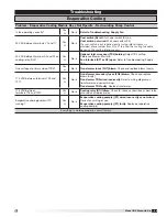
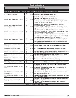
Page 40: ...otor amp draw and correct as necessary Damper limit switch D1L not closed Damper stuck closed or actuator failed Repair damper interference or replace actuator Exhaust fan contactor not powered Close or wire exhaust switch reset exhaust overload or replace faulty exhaust contactor 24 VAC across A2 and A1 on the supply contactor ST1 Yes È No Æ RF relay failure Check for loose connection or bent rel...

Page 41: ...o Æ Reverse fan rotation Reference Supply Fan Start Up Filters dirty or clogged No È Yes Æ Clean or replace filters Reference Maintenance General Filters Belt slipping or broken No È Yes Æ Replace or tighten belt Reference Maintenance General V Belt Drives Fan speed too low No È Yes Æ Adjust drives as needed Reference Supply Fan Start Up section System static losses too high No È Yes Æ Reduce losse...

Page 42: ...furnace controller and one 2 stage furnace 4 1 uses two 4 1 modulating furnaces controlled in parallel High turndown furnaces in a series configuration use one high turndown furnace and one 2 stage furnace High turndown furnaces in a parallel configuration use two high turndown furnaces controlled in parallel Three Furnace Unit 12 1 uses one 4 1 modulating furnace one 2 stage furnace and one 1 sta...

Page 43: ...nce Blower Start Up Fan Interlock ST1 or RF open Refer to Troubleshooting Supply Fan Line voltage at primary side of TR3 Yes È No Æ Transformer fuses FU7 blown Check and replace blown fuse s 115 VAC between terminals 102 and 101 Yes È No Æ Transformer secondary fuses FU8 blown Check and replace blown fuse s Transformer TR3 wired incorrectly Refer to wiring diagram on transformer and correct wiring...

Page 44: ...on auto drain timer set correctly Yes È No Æ Set time ranges to the values shown on the ladder diagram Auto drain timer in drain mode No È Yes Æ Wait for the drain mode timer to expire usually 10 minutes 24 VAC between terminals 8 and 61 Yes È No Æ Auto drain timer TC wiring issue Inspect and correct wiring issue Auto drain timer TC faulty Replace auto drain timer Evaporative cooling module sump fi...

Page 45: ...t breaker If circuit breaker continues to trip inspect circuit for improper wiring or grounding Single pass transformer TR2 failed Replace cooling transformer 24 VAC between terminals 8 and 61 Yes È No Æ Cooling relay RC failure Check for loose connections or bent relay pins repair or replace relay Water flowing to media Yes È No Æ Manual ball valve closed Open and adjust ball valve Single pass val...

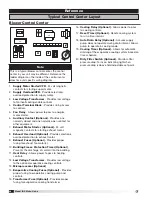
Page 46: ...ows power to pass to heating controls 12 Low Voltage Transformer Provides low voltage to the optional evaporative cooling controls 13 Microprocessor Optional 14 Evaporative Cooling Fuses Optional Provides proper fusing to evaporative cooling pump and controls 15 Transformer Fuse Optional Provides proper fusing for evaporative cooling transformer Note This is a typical blower control center the con...

Page 47: ...sor ________ Actual Setting Typical setting 75ºF 23 9ºC Building Freeze Protection Typical setting 5 minutes 35ºF 1 7ºC Dirty Filter Gauge ________ Actual Setting Typical setting varies Start Up Indirect Gas Furnace 1 o Determine furnace control type High Turndown 8 Stage 4 1 Modulation o Check supply gas pressure ________ Maximum ________ Minimum ________ Actual o Set the High Manifold pressure _...

Page 48: ...____________________________________ _________________________________________________ _________________________________________________ _________________________________________________ _________________________________________________ Date ___________________Time _____________ AM PM Notes ___________________________________________ _________________________________________________ ______________...

Reviews: