9
Energy Recovery Ventilator
CAUTION
If any of the original wire as supplied with the
appliance must be replaced, it must be replaced
with wiring material having a temperature rating of
at least 105ºC.
CAUTION
High voltage wiring is run in the top roof panel(s)
of this unit. Do not install sensors or other devices
through the top panel(s).
WARNING
To prevent injury or death due to electrocution or
contact with moving parts, lock disconnect switch
open.
Most factory supplied electrical components are
prewired. To determine what electrical accessories
require additional field wiring, refer to the unit specific
wiring diagram located on the inside of the unit
control center access door. The low voltage control
circuit is 24 VAC and control wiring should not exceed
0.75 ohms.
Refer to Field Control Wiring Length/Gauge table for
wire length maximums for a given wire gauge.
Control wires should not be run inside the same
conduit as that carrying the supply power. Make sure
that field supplied conduit does not interfere with
access panel operation.
If wire resistance exceeds 0.75 ohms, an industrial-
style, plug-in relay should be added to the unit
control center and wired in place of the remote
switch (typically between terminal blocks R and G
on the terminal strip (refer to Typical Control Center
Components). The relay must be rated for at least
5 amps and have a 24 VAC coil. Failure to comply
with these guidelines may cause motor starters to
“chatter” or not pull in which can cause contactor
failures and/or motor failures.
Field Control Wiring Length/Gauge
Total
Wire Length
Minimum
Wire Gauge
125 ft.
18
200 ft.
16
300 ft.
14
450 ft.
12
1
2
3
4
7
5
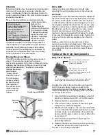
Exploded Detail
of Terminal Strip
6
Typical Control Center Components
1. Main Disconnect (non-fusible, lockable)
2. Motor Starter – Exhaust Air Fan
3. Motor Starter – Outdoor Air Fan
4. Motor Contactor – Energy Wheel
5. 24 VAC Control Transformer
6. 24 VAC Terminal strip
7. Fuses for blower motors

