104
Test Operation, Troubleshooting and Maintenance
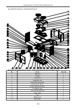
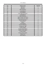
No.
Name
Quantity
14
Pressure Protect Switch
1
15
Pressure Protect Switch
1
16
Pressure Sensor
1
17
Dry Evaporator
1
18
4 Way Valve Coil
1
19
Pressure Protect Switch
1
20
Pressure Protect Switch
1
21
Pressure Protect Switch
1
22
Pressure Sensor
1
23
Pressure Protect Switch
1
24
Handle
4
25
Steam current Switch
1
26
Strainer
4
27
Right Side Plate
1
28
Electric Expand Valve Fitting
1
29
Gas-liquid Separator
2
30
Compressor and Fittings
2
31
Electrical Heater(Compressor)
2
32
Electrical Heater(Compressor)
2
33
Base Frame Assy
1
34
Electrical Heater (Chassis)
2
35
Electronic Expansion Valve
2
36
Electric Expand Valve Fitting
1
37
Temp Sensor Sleeving
2
38
Main board
2
39
Main board
2
40
Rectifier bridge
2
41
Right Front Panel
1
42
Left Front Panel
2
43
Left Front Panel
1
44
Electric Box Assy
1
45
Terminal Board
1
46
Terminal Board
1
47
Reactor
1
48
Bottom Cover Plate
1
49
Intermediate relay
2
50
Terminal Board
1
51
Phase sequence protector
1
52
Terminal Board
1
53
Filter board
2
54
Main board
1
55
Electric Box Assy
1
56
Temperature Sensor Support
1
Summary of Contents for LSQWRF35VM/NaA-M
Page 5: ...1 Product Product...
Page 18: ...14 Unit Control Unit Control...
Page 29: ...25 Unit Installation Unit Installation...
Page 58: ...54 Unit Installation 3 5 7 Electric wiring digram 1 LSQWRF35VM NaA M...
Page 59: ...55 Unit Installation 2 LSQWRF60VM NaA M LSQWRF65VM NaA M...
Page 60: ...56 Unit Installation 3 LSQWRF35VM NhA M...
Page 61: ...57 Unit Installation 4 LSQWRF60VM NhA M...
Page 62: ...58 Unit Installation 5 LSQWRF130VM NhA M...
Page 63: ...59 Unit Installation...
Page 64: ...60 Unit Installation The electric wiring diagrams on the unit always prevail...


