background image

GENERAL

1. I will not fly my model aircraft in sanctioned events, air
shows, or model flying demonstrations until it has been
proven to be airworthy by having been previously
successfully flight tested.

2. I will not fly my model aircraft higher than approximately
400 feet within 3 miles of an airport without notifying the
airport operator. I will give right of way to, and avoid flying in
the proximity of full-scale aircraft. Where necessary an
observer shall be used to supervise flying to avoid having
models fly in the proximity of full-scale aircraft.

3. Where established, I will abide by the safety rules for the
flying site I use, and I will not willfully and deliberately fly my
models in a careless, reckless and/or dangerous manner.

7. I will not fly my model unless it is identified with my name
and address or AMA number, on or in the model.

9. I will not operate models with pyrotechnics (any device
that explodes, burns, or propels a projectile of any kind).

RADIO CONTROL

1. I will have completed a successful radio equipment ground
check before the first flight of a new or repaired model.

2. I will not fly my model aircraft in the presence of
spectators until I become a qualified flier, unless assisted by
an experienced helper.

3. I will perform my initial turn after takeoff away from the pit
or spectator areas, and I will not thereafter fly over pit or
spectator areas, unless beyond my control.

4. I will operate my model using only radio control frequencies
currently allowed by the Federal Communications Commission.

Since the PT-17 Military Stearman ARF qualifies as a “giant-
scale” model and is therefore eligible to fly in IMAA events,
we’ve included excerpts from the IMAA Safety Code.

Definition: For the purpose of the following IMAA Safety
Code, the term “Giant-Scale” shall refer to radio controlled
model aircraft, either scale or non-scale, which have a
wingspan of 80 inches or more for monoplanes and 60
inches or more for multi-winged model aircraft and have a
ramp weight (fueled and ready to fly) of 55 lbs. or less.

Section 1.0: SAFETY STANDARD
1.1 Adherence to Code:This safety code is to be strictly followed

1.2 The most current AMA Safety Code in effect is to be
observed. However, the competition sections of the code
may be disregarded.

Section 3.0: SAFETY CHECK
3.4 Flight Testing: All Giant-Scale R/C aircraft are to have
been flight-tested and flight trimmed with a minimum of six
flights before the model is allowed to fly at an IMAA
Sanctioned event.

3.5 Proof of Flight: The completing and signing of the
Declaration section of the Safety Inspection form by the pilot
(or owner) shall document as fact that each aircraft has
been successfully flight-tested and proven airworthy prior to
an IMAA event.

Section 5.0: EMERGENCY ENGINE SHUT OFF (kill switch)
5.1 All magneto spark ignition engines must have a coil
grounding switch on the aircraft to stop the engine. This will also
prevent accidental starting of the engine. This switch shall be
readily available to both pilot and helper. This switch is to be
operated manually and without the use of the radio system.

5.2 Engines with battery power ignition systems must have a
switch to turn off the power from the battery pack to disable the
engine from firing.This will also prevent accidental starting of the
engine. This switch shall be readily available to both pilot and
helper. This switch shall be operated manually and without the
use of the Radio System.

5.3 There must also be a means to stop the engine from the
transmitter. The most common method is to close the
carburetor throat completely using throttle trim; however,
other methods are acceptable. This requirement applies to
all glow/gas ignition engines regardless of size.

Section 6.0: RADIO REQUIREMENTS
6.1 All transmitters must be FCC type certified.

6.2 FCC Technician or higher-class license required for 6
meter band operation only.

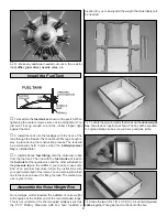
❏ 

1. Fuelproof all areas exposed to fuel or exhaust

residue such as the cowl mounting blocks, wing
saddle area, etc.

❏ 

2. Check the C.G. according to the measurements

provided in the manual.

❏ 

3. Be certain the battery and receiver are securely

mounted in the fuse. Simply stuffing them into place
with foam rubber is not sufficient.

❏ 

4. Extend your receiver antenna and make sure it is in

the antenna tube.

❏ 

5. Balance your model 

laterally.

❏ 

6. Use thread-locking compound to secure critical

fasteners such as the set screws that hold the wheel
axles to the struts, screws that hold the carburetor arm
(if applicable), screw-lock pushrod connectors, etc.

❏ 

7. Add a drop of oil to the wheel axles.

❏ 

8. Make sure all hinges are securely glued in place.

CHECK LIST

IMAA SAFETY CODE (excerpts)

33

Summary of Contents for PT-17 Stearman

Page 1: ...the place of purchase To make a warranty claim send the defective part or item to Hobby Services at this address Hobby Services 3002 N Apollo Dr Suite 1 Champaign IL 61822 USA Include a letter statin...

Page 2: ...ions to the PT 17 Military Stearman ARF visit the Great Planes web site at www greatplanes com Open the Airplanes link then select the PT 17 Military Stearman ARF If there is new technical information...

Page 3: ...sanctioned sites and events Additionally training programs and instructors are available at AMA club sites to help you get started the right way Contact the AMA at the address or toll free phone numbe...

Page 4: ...to decide what type of glue to use When a specific type of adhesive works best for that step the instructions will make a recommendation Whenever just epoxy is specified you may use either 30 minute...

Page 5: ...evator 17 Top Wing Panels L R 18 Bottom Wing Panels L R w Ailerons Qty 4 40 Threaded Metal Clevis 4 3 16 x 2 Axle 2 Screw Lock Pushrod Connector 1 4 40 Blind Nuts 20 4 40 Nuts 4 8 32 Blind Nuts 9 5 16...

Page 6: ...ial Eng Hobby Supplier GPMA2807 Pilot Hobby Supplier GPMA2808 Wheel Covers Hobby Supplier GPMA2809 Windscreens Hobby Supplier GPMA2810 Cabane Set Hobby Supplier GPMA2811 Interplane Strut Set Hobby Sup...

Page 7: ...ots Hint If you have one use a high speed rotary tool to drill the holes 2 Use a sharp 11 blade to cut a strip of covering from the hinge slots in the wing and aileron 3 Cut seventeen 3 4 x 1 19 x 25m...

Page 8: ...ue into the joiner pockets in the wing This can be done by applying the glue into the pocket with a small stick Apply glue to the pocket the joiner and the root rib of the wing Before the glue cures s...

Page 9: ...hen positioned properly the control horn will rest on a plywood plate in the aileron Mark the location of the mounting holes onto the aileron Drill a 1 16 1 6mm hole on the marks drilling through the...

Page 10: ...h the holes in the wing Trace the outline of the plate onto the covering with a felt tip pen Use a sharp 11 blade and refer the ExpertTip that follows to cut the covering inside the lines you have dra...

Page 11: ...to the fuselage 4 Cut the covering and the wood block from the back of the horizontal stabilizer saddle 1 Temporarily attach the lower wing to the fuselage with the 1 4 20 nylon bolts Slide the horizo...

Page 12: ...Test fit the fin into the fuselage Check to be sure the fin is perpendicular to the stab If it is not sand the side of the fin to make minor adjustments Once you are satisfied with the fit glue the f...

Page 13: ...inges into the rudder and then fit the rudder to the fin and fuselage Make any adjustments that may be needed to the slot in the rudder When you are satisfied everything fits well put a small amount o...

Page 14: ...yet 5 Position the N strut to the bracket Located on the strut is a piece of masking tape with an arrow that indicates the top front of the strut 6 Attach the strut to the bracket as shown with a 4 40...

Page 15: ...be drilling into the hardwood rails located in the fuselage 15 Install and then remove a 4 x 1 2 13mm sheet metal screw into each of the four holes Apply a couple drops of thin CA into each of the ho...

Page 16: ...andle between the struts 7 On the remaining handle part install a 4 40 blind nut into each of the corner holes 8 Place the two N struts into the handle Put the handle top onto the part of the handle h...

Page 17: ...4 8mm hole through the firewall in line with the throttle arm on the carburetor 5 Locate the 24 610mm gray plastic pushrod tube and cut it 12 3 4 324mm in length Sand one end of the tube with 220 gri...

Page 18: ...of the block is flush with the side of the fuselage 2 Slide the fiberglass cowl onto the front of the fuselage Cut the cowl as needed to allow the cowl to fit over the engine 3 On the front of the dum...

Page 19: ...e dummy radial engine Cut small amounts of the dummy radial engine at a time When complete there will only be a small amount of the back of the dummy radial engine that needs to be cut away 6 Drill tw...

Page 20: ...f microballoons and 6 minute epoxy to the inside of the cowl and dummy radial engine This will securely attach the two parts 12 Apply a piece of masking tape to the fuselage in line with the cowl moun...

Page 21: ...ill attach to the pressure tap on the muffler If you choose to use some kind of an external fuel valve follow the instructions with your particular brand of fuel valve You can also install a third lin...

Page 22: ...les making sure that the head of the screw is flush or slightly below the top of the wood block 6 Place the box on top of the rails and between the triangle stock located on the firewall Drill four 1...

Page 23: ...cover to the wheel with four 2 x 3 8 9 5mm screws The holes in the wheel cover align with the holes that are pre drilled in the wheel Note Tighten the screws snugly to the wheel cover Do not try to ti...

Page 24: ...l and remove a servo mounting screw into each hole Apply a couple drops of thin CA into the holes to harden the threads When the glue has cured permanently mount the servo to the servo tray 6 Center t...

Page 25: ...5mm screw into each of the holes Then apply a couple of drops of thin CA into the holes to harden the threads Once the glue has cured the tray can be mounted with four 2 x 3 8 9 5mm sheet metal screws...

Page 26: ...ng the need to cut any covering in order to expose wood for a good bond 3 Cut the windscreens on the cut lines Glue them in place with R C 56 canopy glue 4 Your kit includes two pilots Make a bottom f...

Page 27: ...1 8 79mm On the marks drill a hole through the fin with a 5 64 2mm drill 3 Drill a 5 64 2mm hole through the block at the back of the fuselage 4 Cut a piece of the elastic cord 50 1270mm long This le...

Page 28: ...op of CA on the cord then insert it into the hole shown 10 Bring the elastic cord around the top of the forward strut and pull it back toward the fuselage Glue the cord into the hole next to the hole...

Page 29: ...o the photographs on the box the following pictures should help you in the placement of the decals 1 Use scissors or a sharp hobby knife to cut the decals from the sheet 2 Be certain the model is clea...

Page 30: ...ccurately measure and set the control throw of each control surface as indicated in the chart that follows If your radio does not have dual rates we recommend setting the throws at the low rate settin...

Page 31: ...r maneuvers No matter if you fly at an AMA sanctioned R C club site or if you fly somewhere on your own you should always have your name address telephone number and AMA number on or inside your model...

Page 32: ...way from high heat sparks or flames as fuel is very flammable Do not smoke near the engine or fuel and remember that engine exhaust gives off a great deal of deadly carbon monoxide Therefore do not ru...

Page 33: ...ections of the code may be disregarded Section 3 0 SAFETY CHECK 3 4 Flight Testing All Giant Scale R C aircraft are to have been flight tested and flight trimmed with a minimum of six flights before t...

Page 34: ...en you re ready point the model straight down the runway hold a bit of up elevator to keep the tail on the ground to maintain tailwheel steering and then gradually advance the throttle As the model ga...

Page 35: ...sarily to improve your skills though it is never a bad idea but more importantly so you do not surprise yourself by impulsively attempting a maneuver and suddenly finding that you ve run out of time a...

Page 36: ...____________ Where Purchased _________________________ Date Construction Started __________________ Date Construction Finished _________________ Finished Weight __________________________ Date of Firs...

Reviews: