background image

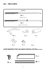
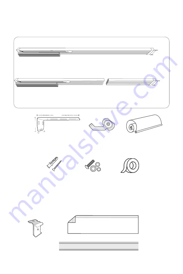
ALL   INCLUDED 

x1

x1

xn

I------

-----

-----I

I-----------------I

1.2

(29mm)

1.2

(29mm)

s

1

 xn

xn

l

 xn

  ACCESSORIES FOR VALANCE INSTALLATION

(OPTIONAL)

xn

xn

xn

u

 xn

xn

6.3

(163mm)

2.2

(58mm)

2.2

(55mm)

2

3.2

(80mm)

Standard Version

Optional

Extension Track version

3.2

(80mm)

Summary of Contents for 68930

Page 1: ...Version 1 0 Date 28 Feb 2022 PANEL TRACK BLIND INSTRUCTION 68930...

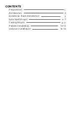
Page 2: ...1 Preparation 2 Accessories Extension Track Installation 3 Valance Installation 14 16 12 13 Panels Installation CONTENTS 4 7 Side Wall Mount 8 11 Ceiling Mount...

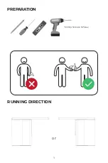
Page 3: ...PREPARATION RUNNING DIRECTION or Drilling hole size 0 2 6mm 1...

Page 4: ...1 f xn I I I I 1 2 29m m 1 2 2 9 m m s1 xn c xn l xn ACCESSORIES FOR VALANCE INSTALLATION OPTIONAL h xn p xn i xn u xn b xn 6 3 163mm 2 2 58mm 2 2 55mm 2 3 2 80mm Standard Version Optional Extension T...

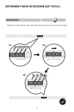
Page 5: ...Align the seam of the two pieces of track and turn over to the back EXTENSION TRACK ACCESSORIES OPTIONAL Loosen the screw Move it to the middle 3 Tighten the screws 01 02 03...

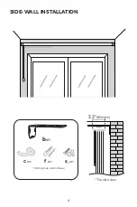
Page 6: ...The side view Drilling hole size 0 2 6mm SIDE WALL INSTALLATION f xn s1 xn bxn c xn 3 2 80mm 4...

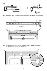
Page 7: ...rizontal line that needs to be drilled 1 25mm 1 10 254mm 03 According to the hole has been drilled mark the points to other holes then drill the hole 16 400mm 16 400mm 5 Drilling the hole positions ar...

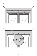
Page 8: ...6 03...

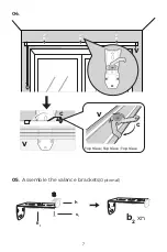
Page 9: ...05 Assemble the valance brackets Optional 04 v 7 v c v Top View Top View Top View c b2 xn h s1 b1...

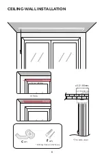
Page 10: ...The side view or here c xn CEILING WALL INSTALLATION f xn 1 6 40mm 3 2 80mm Drilling hole size 0 2 6mm 8 depth 3 2 80mm...

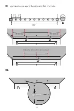
Page 11: ...01 02 Use tape to measure the size and Dril the hole 1 1 10 3 2 80m m 16 406mm 16 406mm 5 125m m c f Drilling the hole positions are equidistant 9 u u u...

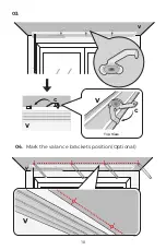
Page 12: ...03 04 Mark the valance brackets position Optional v 10 v v c c v Top View...

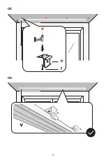
Page 13: ...05 06 11 f h...

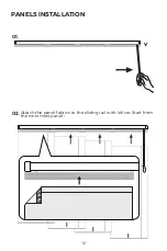
Page 14: ...PANELS INSTALLATION 01 02 Attach the panel fabrics to the sliding rail with Velcro Start from the innermost panel 12 v l l l l...

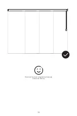
Page 15: ...The blind has been programmed already please use directly 13...

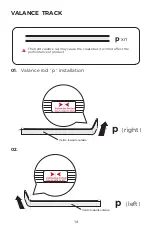
Page 16: ...TRACK p xn 90 p right p left 90 The bent valance rail may cause the crease but it will not affect the performance of product Velcro towards outside Velcro towards outside 01 02 Valance rod p installa...

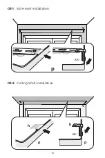
Page 17: ...03 2 v p p h h 03 1 v Side wall installation Celling Wall installation KA 15 p KA...

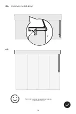
Page 18: ...04 05 Valance installation i The blind has been programmed already please use directly 16...

Reviews: