background image

2

About this Manual

Warnings and Precautions

Warnings and Precautions

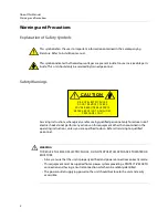
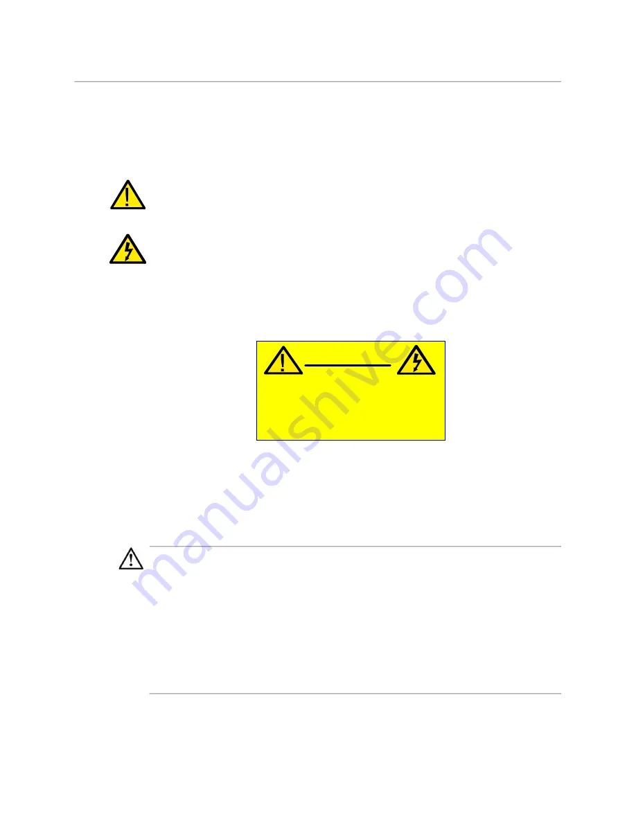
Explanation of Safety Symbols

This symbol refers the user to important information contained in the accompanying 

literature. Refer to installation manual.

This symbol indicates that hazardous voltages are present inside. No user serviceable parts 

inside. This unit should only be serviced by trained personnel.

Safety Warnings

Servicing instructions, where given, are for use by qualified personnel only. To reduce risk of 

electric shock do not perform any actions on this equipment other than contained in the 

operating instructions, unless you are qualified to do so. Refer all servicing to qualified 

personnel.

WARNING


TO REDUCE THE RISK OF ELECTRIC SHOCK, DO NOT EXPOSE THIS APPLIANCE TO WATER OR 

MOISTURE.

• Always ensure that the unit is properly earthed and power connections correctly made. 
• This equipment must be supplied from a power system providing a PROTECTIVE EARTH 

connection and having a neutral connection which can be reliably identified.

• The power outlet supplying power to the unit should be close to the unit and easily 

accessible.

CAUTION

RISK OF ELECTRIC SHOCK
DO NOT REM OVE COVERS

NO USER SERVICEABLE PARTS

REFER SERVICING TO QUALIFIED

PERSONNEL ONLY


Summary of Contents for MAV REMOTE

Page 1: ...Installation Manual Issue 2 Rev 1 2021 07 21 MAV REMOTE MAV REMOTE SOLUTIONS FOR KAHUNA KULA MASTERPIECE AND AMPP ...

Page 2: ...ject to change without notice Terms and Conditions Please read the following terms and conditions carefully By using MAV Remote documentation you agree to the following terms and conditions Grass Valley hereby grants permission and license to owners of MAV Remote to use their product manuals for their own internal business use Manuals for Grass Valley products may not be reproduced or transmitted ...

Page 3: ...ck Mount 8 19 Rack Mount using two Mav Remote units with a Joining Plate 8 4 Cabling and Connections 9 Mav Remote Connections 9 Mav Remote Connections 9 MAV GUI Connections continued 10 Connecting a Touch Screen Monitor to the Mav Remote 11 For Kula Connection Diagram for Kula working with K Touch 12 For Kahuna Connection Diagram for Mav Remote Production 13 For Masterpiece Connection Diagram for ...

Page 4: ...iv Table of Contents 8 Specifications 25 Mav Remote Specifications 25 Contact Us 27 ...

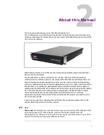
Page 5: ...tcher solution Mav Remote is a cost effective dedicated hardware solution that delivers the solid and reliable operational benefits of the Maverik or Kula Control surface Eliminating the need to be in the same location as the video processing equipment the Mav Remote is simply connected to the Kahuna or Kula Video Processing mainframe across a network connection It provides full control of the mai...

Page 6: ...rm any actions on this equipment other than contained in the operating instructions unless you are qualified to do so Refer all servicing to qualified personnel WARNING TO REDUCE THE RISK OF ELECTRIC SHOCK DO NOT EXPOSE THIS APPLIANCE TO WATER OR MOISTURE Always ensure that the unit is properly earthed and power connections correctly made This equipment must be supplied from a power system providi...

Page 7: ...he following standards EN 55032 2012 Class A Electromagnetic Compatibility of Multimedia Equipment Emission Requirements EN 55103 2 2009 Electromagnetic compatibility Product family standard for audio video audio visual and entertainment lighting control apparatus for professional use Immunity EN 61000 3 2 2014 Class A Limits for Harmonic Current Emissions EN 61000 3 3 2013 Limitation of Voltage C...

Page 8: ...nded WARNING This equipment is compliant with Class A of CISPR 32 In a residential environment this equipment may cause radio interference On Receipt of the Mav Remote The equipment is supplied in dedicated packaging provided by the manufacturer and should not be accepted if delivered in inferior or unauthorized materials Carefully unpack the system components and check them against the packing li...

Page 9: ...box will contain the following 1x Mav Remote Unit 2x External Power Supplies 1x HDMI Cable with cable tie to attach to Mav Remote body USB memory device with all relevant documentation Note Note Installation and User Manuals are supplied regardless of system components purchased ...

Page 10: ...6 About this Manual What is supplied with Kahuna Maverik ...

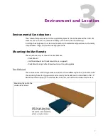
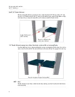
Page 11: ...ere are three ways to mount the Mav Remote Desk Mount Half Rack Mount with rack mount tray as support Rack Mount using 2x Mav Remote units with a joining plate Desk Mount The rack mount ear mounting brackets can be set to two different positions horizontal with the mounting holes facing upwards and vertically for Rack Mount as described in the 19 Rack Mount description this will allow the unit to ...

Page 12: ...o the rack sides 19 Rack Mount using two Mav Remote units with a Joining Plate Two Mav Remote units can be joined together using a joining plate which allows the units to span across the full width of the rack and fasten to the rack without the support of a rack tray Note Note The Mav Remote must have ventilation to allow cooling and must not be installed into an enclosed space The unit is secured...

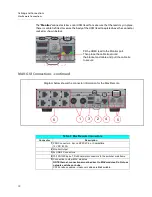
Page 13: ...ller means of control when used with MAV modules The Mav Remote has 2 external PSU connectors one PSU can power the MAV GUI the other PSU is for redundancy The Mav Remote has a network port which connect directly to the switcher mainframe The Mav Remote has 8x Comms ports and can have up to 16 individual MAV modules connected to it Mav Remote Connections 6 Comms Ports to connect to MAVs on the con...

Page 14: ...tie around the bracket and cable and pull the cable tie to secure Diagram below shows the connector information for the Mav Remote 1 2 3 4 5 5 Table 1 Mav Remote Connectors Connector Description 1 PSU Connectors Kycon KPPX 4Pin or Compatible 12V DC 8 33A 2 Monitor Output 3 2x USB 2 Connectors 4 10 100 1000 base T RJ45 network connectors to the switcher mainframe 5 Connection to other MAV modules N...

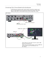
Page 15: ...r will have to have a 1920 x 1080 display resolution and it is recommended that the monitor be larger than 21 inches Mav Remote MON monitor output port USB port When using a touch screen When using a non touch screen monitor connect a USB Mouse to control the menus When using a touch screen monitor connect the USB lead from the monitor to one of the USB ports on the HDMI to DVI or HDMI Lead USB Le...

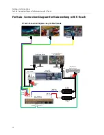
Page 16: ... Connectors Touch Screen Monitor HDMI USB Network Network Network Kula 2M E Control Surface BNC from Kula Output 3G HDMI to SDI 3G SDI to HDMI HDMI HDMI BNC to Kula Input Touch Screen Monitor with K Touch HDMI USB HDMI USB Network PGM Out PVW Out MV Out PGM PVW Multiviewer Mav Remote Rear Connectors Kula Control Surface Connectors HDMI USB K Touch Connection Diagram using the Mav Remote ...

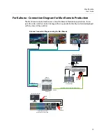
Page 17: ...n facility and can be deployed with any Grass Valley switcher Touch Screen Monitor HDMI USB Network Network Network Kahuna Maverik Main Production Control Surface Remote Kahuna Maverik Control Surface Touch Screen Monitor HDMI USB HDMI USB Network PGM Out PVW Out MV Out PGM PVW Multiviewer Mav Remote Rear Connectors Kahuna Connection Diagram using the Mav Remote HDMI USB Remote Network Connection ...

Page 18: ...am for Remote Production Touch Screen Monitor HDMI USB Network Network Network Masterpiece Control Surface Touch Screen Monitor HDMI USB HDMI USB Network PGM Out PVW Out PGM PVW Mav Remote Rear Connectors Masterpiece Connection Diagram using the Mav Remote Remote Network Connection to Mainframe Masterpiece Mainframe ...

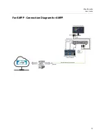
Page 19: ...15 Mav Remote User s Guide For AMPP Connection Diagram for AMPP ...

Page 20: ...16 Cabling and Connections For AMPP Connection Diagram for AMPP ...

Page 21: ...d shut Do not attempt to open the power supply cases Note Note Make sure that the mains power is turned Off before connecting the PSU to the Mav Remote The power supply connector plug that connects to the Mav Remote is a 4 pin Snap and Lock type care should be taken when connecting and un connecting from the Mav Remote Caution Do not allow the power supplies to hang freely from the Mav Remote Make...

Page 22: ...18 Power Supplies Mav Remote External Power Supplies ...

Page 23: ...ke the one displayed below There is no mainframe or logical switcher displayed in the menu Find out the IP address of the mainframe you want to connect to then on the GUI attached to the Mav Remote touch the Panel Config menu link button In the Panel Config main menu touch the IP Mainframes menu link button The IP Mainframes menu is used to connect to other mainframes on a network If a mainframe i...

Page 24: ...frame is on a different network you will need to enter the gateway IP address that the mainframe is on in the Outgoing Gateway parameter and add the gateway that the Mav Remote is on in the Return Path Gateway parameter When this has been done touch the Add IP Network button The mainframe should now be displayed in the menu Touch the Arrow Up button to go back to the Connect menu The Connect menu ...

Page 25: ...ame Config button is red this means that the mainframe software is different to the Mav Remote software Touch the Mainframe Config button and a dialog will be displayed asking you if you want to upgrade the Mav Remote to the current mainframe software version touch Yes to upgrade the software Once complete touch the Switcher Login button to log into the system ...

Page 26: ...p and Configure AMPP Configuring AMPP Configuring Enter the IP address details of the AMPP system you are connecting to As new Maverik AMPP Control and AMPP enhancements become available the unit can be upgraded ...

Page 27: ...Mav Remote Dimensions Table 2 Mav Remote Dimensions Width Depth Height 9 44 inches 239 9 mm 12 95 inches 329 mm 2 00 inches 50 7 mm including feet Weight TBC lbs TBCkg Environmental 41 to 104 F 5 to 40 C non condensing ...

Page 28: ...24 Dimensions Mav Remote Dimensions ...

Page 29: ...MAV modules Do Not use network switches or hubs CAT5 or above cables crossover cables are Not suitable Table 4 Mav Remote Power Supplies Power Supply Description To the Mav Remote 2x Fully independent external PSU modules with separate mains power feeds via 2x 10A IEC leads Output from each PSU 12V DC 100W via Kycon KPPX 4 Pin or Compatible connectors to the Mav Remote 2 supplied as standard per M...

Page 30: ...26 Specifications Mav Remote Specifications ...

Page 31: ...in a local phone number for the support center nearest you please consult the Contact Us section of Grass Valley s website www grassvalley com An on line form for e mail contact is also available from the website Corporate Head Office Grass Valley 3499 Douglas B Floreani St Laurent Quebec H4S 2C6 Canada Telephone 1 514 333 1772 Fax 1 514 333 9828 www grassvalley com ...

Reviews: