


Kayak HD — Installation Planning Guide
37
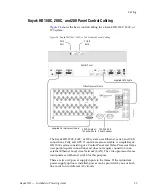
Cabling
One Ethernet connector must connect to the Control Panel. It may go
through a switch to make the Control Panel connection, but at least one
connector must be connected from the Frame to the Control Panel
somehow.
One Ethernet connector may be connected to the Facility LAN if desired.
The other two Ethernet connectors may be connected to other devices if
needed.
Note
If you do connect these extra Ethernet connectors to other devices, please
note that these other devices will not communicate if the switcher frame is
turned off for any reason. For that reason, it is preferable to connect Ethernet
ports coming from the switcher only to other devices that are switcher-
related.
Factory Network Settings
The default factory setting for the IP address is
•
192.168.0.70 for the video processor frame
•
192.168.0.73 for the control panel
The Device Setup menu allows to change the IP address. It is only allowed
to change the last octet of the IP address (to accommodate Kayak HDs on
the same network).
Note
In order to integrate Kayak HD devices into an existing network, ask the local
network administrator for the subnet mask of the network. Before changing
IP addresses always set the subnet masks of the Kayak HD devices to the
mask of the local network. If all changes are made and a frame is not visible
to the panel, press 'Rescan' in the “Device Control” menu of the panel.
Video Cabling for all Kayak HD Switchers
All Kayak HD system video inputs and outputs are configurable. For
cabling configuration flexibility, each external primary input can be
mapped to any Kayak HD panel source select button, as can each internal
video system source. Any Kayak HD system video signal, such as M/E
program, preview, clean feed, or PGM/PST, can be mapped to any output
bus to be accessed on a specific connector, or an output bus can act as an
auxiliary bus.
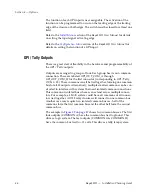
Inputs
Non-looping video inputs on the back of the Video Processor frame are
numbered 1 through 24 and 25 through 48 on the 4 RU frame. Each accepts
a 270 MHz serial digital video signal, or 1.485 Gb. The number of inputs
that are active depends on the number of full mix/effects or I/O Expansion
modules that are installed in the chassis. There are 24 inputs active for
every mix/effects module and expansion module installed.