background image

36

Creative Grading Camera Control System User’s Guide (v1.4)

Chapter 4  - CGA Operation

4.5.3  CGP configuration menu

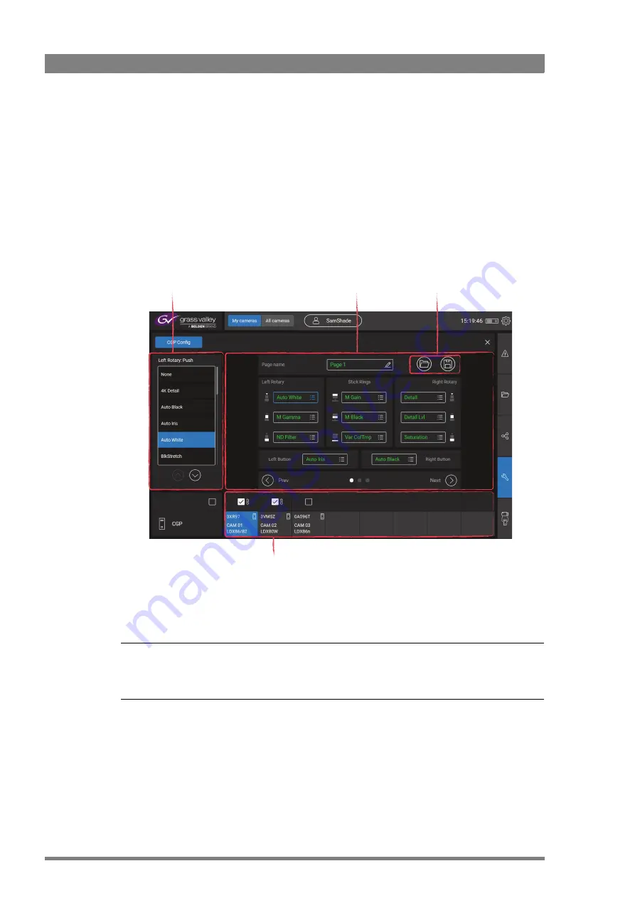
In this menu the assignable buttons of the CGP(s) can be set up. The Assignment area in the 
center of the screen shows the buttons and their (current) assignments. At the top the page 
name is shown.

Tap the pencil icon to enter a name for the page. Tap the Prev or Next to scroll through the 
different pages. Up to three pages of assignments can be set up.

Tap a function to change an assignment (for the selected button). The selection list appears at 
the right side of the screen. Select a function from this list.

At the bottom the CGP selection bar is shown. By default the current/active CGP is highlighted 
and selected but you can also tap a different CGP to change its assignments. 

Tip


Create a group of CGPs by ticking one ore more checkboxes above the corresponding CGPs to 
change assignments for the group.

s
m

Selection list

Select a function from the 
list for the selected button

Assignment area

Current assignments for 
all assignable buttons

CGP selection

Select one or more CGP(s) to 
change the button assigments

Load/Save buttons

Load or save a CGP 
configuration

Summary of Contents for Creative Grading

Page 1: ...13 00088 000 August 2020 v1 4 Creative Grading User s Guide Camera Control System ...

Page 2: ...area is likely to cause interference in which case the user at his own expense will be required to take whatever measures may be required to correct the interference Copyright and Trademark Notice Grass Valley GV and the Grass Valley logo and or any of the Grass Valley products listed in this document are trademarks or registered trademarks of GVBB Holdings SARL Grass Valley USA LLC or one of its ...

Page 3: ...ng up the server 12 2 2 3 Setting up the network 12 2 2 4 Adding a storage USB Flash Drive 12 2 3 Installing the CGA Creative Grading Application 13 2 3 1 Connecting the tablet computer 13 2 3 2 Installing the app 13 2 4 Installing the CGP Creative Grading Panel 14 2 4 1 Connecting power 14 2 4 2 Setting up the network 14 Chapter 3 Setup 3 1 Managing user profiles 15 3 2 Assigning cameras and CGPs...

Page 4: ...40 5 1 4 Snapshot button 41 5 1 5 File management shortcut button 41 5 1 6 Stick 41 5 1 7 Preview button 42 5 1 8 CGA view mode buttons 42 5 1 9 Free button 42 5 1 10 CGA menu shortcut buttons 43 5 1 11 RGB grading rotaries 43 5 1 12 Left function buttons 43 5 1 13 Assignable controls 44 5 2 CGP local display 46 5 2 1 Tally bar 46 5 2 2 Camera identification area 46 5 2 3 RGB Grading rotaries area...

Page 5: ...g Camera Control System User s Guide v1 4 5 7 2 CGP 500 Creative Grading Panel 57 7 2 1 Specifications 57 7 2 2 Mounting 57 7 2 3 Dimensions 58 7 2 4 Connectors 59 7 2 5 Studio signalling 61 7 2 6 Powering the CGP 63 ...

Page 6: ...ations are subject to change without notice If you have questions about Grass Valley environmental and social involvement WEEE RoHS REACH etc please contact us at environment grassvalley com Packing for return If a unit is being returned to Grass Valley for servicing try to use the containers and materials of the original packaging Attach a tag indicating the type of service required return addres...

Page 7: ...impaired the apparatus must be made inoperative and secured against any unintended operation The appropriate servicing authority must then be informed Warnings Warnings indicate danger that requires correct procedures or practices to prevent death or injury to personnel Do not modify this equipment Installation of this equipment must only be performed by qualified personnel Do not use any accessor...

Page 8: ...8 Creative Grading Camera Control System User s Guide v1 4 ...

Page 9: ...he purpose of this user s guide is to present a detailed description of how to install set up and operate the Creative Grading system 1 1 2 Compatibility This user s guide describes the functionality of the following system components Make sure that your hardware components are using the listed software versions Refer to the information below for more details about getting more information and dow...

Page 10: ... brain of the system The CCS ONE is required to have the additional functionality of Creative Grading such as tablet connectivity The CCS ONE runs the Creative Grading Engine CGE which is pre installed on the CCS ONE One CCS ONE is required per C2IP subnet and can host up to 99 cameras It runs Windows 10 IoT LTSB which means it can run the latest and greatest network safety tools as demanded by ma...

Page 11: ...ameras Control Server and 1 CGA Creative Grading Application running on a tablet computer for a single shader position 2 1 2 System components The following hardware components are not included in the package and need to be obtained from other sources and or parties Powered PoE Network Switch CCS ONE Cameras Control Server CGA Creative Grading Application CGP 500 Creative Grading Panels Studio cam...

Page 12: ...creen log in with admin as the user name and enter admin as the password Go to Start on the taskbar and go to Settings Network Internet View your network properties and locate the IP IPv4 settings of the LAN Public network interface Copy or write down these settings for later use when installing the CGA app 2 2 3 Setting up the network Connect an Ethernet switch to the C2IP Ethernet port of the CC...

Page 13: ...Apply external power to the tablet computer It is strongly adviced to use an external power supply as most USB to Ethernet adapters draw too much power for the internal battery Switch on the tablet computer 2 3 2 Installing the app Follow these steps to install the Creative Grading App on your tablet conmputer Go to the App Store log in usings your credentials and search for the Grass Valley Creat...

Page 14: ...onnector on the back side of the CGP and connect it to the Ethernet switch make sure it is connected to the C2IP Ethernet port of the CCS ONE If the Ethernet network is not powered connect power to the panel 2 4 2 Setting up the network After applying power to the CGP wait a few seconds for the panel to start up The Creative Grading logo is shown on the display during the start up procedure The CG...

Page 15: ...ssigning your cameras and panels CGPs to create your shader workspace If you already have a user profile tap your name in the list of profiles and tap Select to get started You can always add change and delete your assigned cameras and CGPs in the Cam CGP menu You can delete and rename exisiting user profiles or create a new one The active user profile is indicated by a user icon behind the name T...

Page 16: ...s and CGPs to your workspace On the main screen tap Cam CGP assign on the slide out menu at the bottom right of the screen The following window appears 3 2 2 Assigning cameras To assign a camera system to a tile on the camera selection bar tap the button right above the tile The Select camera windows shows all available camera systems Tap a camera number to select it Camera systems area Camera sel...

Page 17: ...tion can be used when a camera is currently not present but will be at a later stage The camera system is now assigned to the camera tile Continue assigning a CGP to this camera system refer to the next section or assign more camera systems to your workspace It is always possible to change delete or add more cameras or panels later on ...

Page 18: ...GPs show the following information on their local displays Press and hold the Single button for two seconds on the CGP you want to assign to the tile Tip It is not required to assign a CGP to a camera system You can control and operate a camera system without a CGP using only the CGA However for live camera operation it is strongly recommended to assign a CGP Already assigned Already assigned Not ...

Page 19: ...Ps your workspace should look similar to this To exchange the positions of two camera systems tap the button of the first camera then tap the second The cameras switch places including their assigned CGPs if any To delete an assigned camera system tap the button above the camera tile To delete an assigned CGP tap the button below the camera tile ...

Page 20: ...20 Creative Grading Camera Control System User s Guide v1 4 Chapter 3 Setup ...

Page 21: ... view Camera selection bar Select a camera and view some status information Functions area Shows functions and values of the camera different for single view and multi view modes About and CGA Server status Shows important information about the CGA and server safe removal of USB Flash Drives Slide out menus Errors Warnings File Management Share CGP Config and Cam CGP assign menus Navigation menu A...

Page 22: ...Snapshot button Tap this button to take a snapshot of the current settings of all cameras in MyCameras selection Snapshots are stored in the Snapshots section of the File Management menu 4 2 Single camera view The CGA has two camera view modes Single view and Multi view Selecting video functions from the navigation menu works similarly in both view modes Single view is used to operate one camera T...

Page 23: ... the menus and submenus to find the video function you need 4 2 3 Functions area The typical layout of the function area in single view mode is shown below Tap a function in the functions area to change its value A input window appears at the left side of the screen There are three function types A value range for example 1 to 100 or 0 0 to 12 0 dB A value list for example Clear ND1 4 ND1 16 ND1 6...

Page 24: ...rotary to confirm In multi camera mode the CGP rotaries of all cameras become active the rings light blue while each rotary controls its individual camera In multi camera modem when cameras are grouped the CGP rotaries the grouped camera become active the rings light green while each rotary controls the function of all grouped cameras simultaneously Slider for value range functions use the slider ...

Page 25: ... value grid in the center shows the current values of the respective functions To change a function value tap a value in the value grid both its corresponding function in the top row and the camera in the camera selection area are selected 4 3 1 Grouping cameras To operate one or more cameras simultaneously tap the camera number s on the vertical camera selection bar at the left side of the functi...

Page 26: ...tains the video function menu At top level there are 8 menus the first menu is Home then 5 main video operational menus Light Contrast Color Enhance and Automatics and 2 menus for Setup and Diagnostics 4 4 1 Home menu This menu contains a summary of important functions in a compact overview Tap a function tile to change a function s value ...

Page 27: ...s optical Filters Exposure time and finally Gain plus sensitivity By adjusting a light parameter in the lower half of the screen you can immediatly monitor its impact on the amount of light or video signal that travels through the system This is represented by the dark yellow diagram in the center 4 4 3 Contrast menu Contrast is the difference in brightness between light and dark areas of an image...

Page 28: ... such a color temperature gamut and color tint in one overview This menu also contains the color corrector color matrix settings 4 4 5 Enhance menu This menu contains camera functions that enhance the video signal such as Detail Detail Equalizer Texture Skin detail FX filter LedWall filter AnyLight Freeze Reverse Scan CLASS and Lens shading ...

Page 29: ...atics menu This menu contains automated video controls or adjustments such as Auto Iris Auto White Auto White Continuous and FullBlack 4 4 7 Setup menu The setup menu contains items to set up the entire camera system including advanced controls audio routing signal tweaking and special functions ...

Page 30: ...the menu are shown in a small tile in the function area as well as on the monitoring output and or in the viewfinder Additionally you can use the CGA navigation rotary on the CGP to navigate the camera menu turn to scroll and push to select Accessing the XCU base station menu The CGA can be used to remotely access the XCU base station menu In the Setup menu scroll down to navigate to the BaseStati...

Page 31: ...oftware and license information as well as transmission statuses 4 5 Slide out menus The slide out menus contain generic tools and functions that are available in both single and multi view Tap an icon on the bar at the right to slide it out The following menus are available Error warnings menu future use File Management menu Share menu CGP Configuration menu Cam CGP assign menu ...

Page 32: ...ive settings are also managed as a preset file Tip Create a group of cameras by ticking one or more checkboxes next to the camera numbers and manage files simultaneously for the group of cameras Tick the top left checkbox to select all cameras Actions Select a file in the matrix by tapping it and then one of the action buttons at the bottom of the screen Recall copies the selected file to the came...

Page 33: ...ash Drive and tap Select storage Make sure a USB Flash Drive is inserted into a USB port on the CCS ONE The Files box displays directories and only scene files present in the current directory Directory up navigates up one directory level Open directory opens the directory and navigates down one level New directory creates a new directory in the current directory Lock Unlock locks or unlocks the s...

Page 34: ...ot button on the CGA for all cameras in MyCameras Snapshots appear in the Snapshot Matrix where they are stored under a unique sequence number and the date and time of their creation Snapshots are filed per camera in the order of creation newest start at the left Tip Tap the Rename button to rename a snapshot for easier recognition Tap the icon at the top right to view more information about the S...

Page 35: ...will be deleted Snapshots can be protected against removal in case a limit of 10 is reached When a camera is removed from MyCameras its associated snapshots are deleted Snapshots are automatically deleted 48 hours after they were created even when they are protected All snapshots are deleted after a reboot of the CCS ONE If you want to keep it store the snapshot as a Scene file Note Note Snapshots...

Page 36: ... an assignment for the selected button The selection list appears at the right side of the screen Select a function from this list At the bottom the CGP selection bar is shown By default the current active CGP is highlighted and selected but you can also tap a different CGP to change its assignments Tip Create a group of CGPs by ticking one ore more checkboxes above the corresponding CGPs to chang...

Page 37: ...f CGPs by ticking their checkboxes to load the same configuration to all CGPs 4 5 4 Cam CGP assign menu In this menu the Camera systems and CGP panels can be set up Refer to Section 3 2 1 on page 16 for detailed information about this menu File area Manage files directories and storage devices Page selection Select one or more CGP assignment pages to load File name Enter file name and Load or Canc...

Page 38: ...38 Creative Grading Camera Control System User s Guide v1 4 Chapter 4 CGA Operation ...

Page 39: ...otaries Controls for RGB Gain levels upper rings and RGB Black levels or RGB Flare lower rings CGA view mode buttons The Multi and Single buttons toggle between multi and single camera operation on the CGA Left function buttons Change CGP Settings switch on test signals or do a Standard Recall CGP local display Shows important operational and status information such as camera number iris value and...

Page 40: ...k button Push the Panel Lock button to lock the operation panel of the CGP This button lights when the panel is locked On When off all functions of the CGP can be used Call button Push the Call button to send a signal to the connected camera calling for attention The Call button lights when it is activated OR when a call is received from another system part If active push again to switch off A buz...

Page 41: ...n Iris control stick up and down Move the stick up and down to change the Iris lens opening of the camera The display shows the current Iris or F value Preview button Push to view a selected camera signal on a preview monitor Stick upper ring Turn the upper ring below the knob to adjust Master Gain level Stick middle ring Turn the ring to adjust Master Black level Stick lower ring Turn the ring to...

Page 42: ...view mode buttons CGA multi view button This button has a double function when pushed the CGA changes to multi view mode AND this CGP is selected as the active panel The buttons is highlighted CGA single view CGP selection button This button has a double function when pushed the CGA changes to single view mode AND this CGP is selected as the active panel The buttons is highlighted 5 1 9 Free butto...

Page 43: ...atics menu Home menu Diagnostics menu Push the shortcut button repeatedly to navigate through the submenus on the CGA 5 1 11 RGB grading rotaries These three stacked rotary controls vary RGB gain levels upper rotary and R G and B black levels lower rotary The lower rotary can also be set to RGB Flare controls in the CGP Settings on page 48 5 1 12 Left function buttons CGP settings button Push the ...

Page 44: ...ard button again to cancel and close the popup window 5 1 13 Assignable controls These 4 push buttons and 2 stacked rotary controls with push buttons on top can be assigned to any operational camera function The assignments are done in the CGA using the CGP config menu Refer to CGP configuration menu on page 36 for more information Selection buttons These two push buttons operate the associated fu...

Page 45: ... User s Guide v1 4 45 Chapter 5 CGP Operation Next and Previous buttons Use the Prev and Next buttons to scroll through the different pages of assignable buttons functions There are up to three pages of assignments that can be configured 3 ...

Page 46: ... ISO 5 2 2 Camera identification area Shows the camera number and the camera system alias and some connection information to the CGS and the CGA Lens area Shows lens and video gain information RGB Grading rotaries area Shows assignments and values of the rotaries Camera Identification area Shows camera number and alias and CGP connection statuses Assignable controls area Shows assignments and valu...

Page 47: ... Black levels 5 2 4 Lens area This screen area shows Video Gain in dB the iris opening or F value plus Range Extender setting and Auto White Balance indicators 5 2 5 Assignable controls area Top rings control RGB Gain levels Bottom rings control RBG Black levels Range Extender indicator Auto White Balance indicator Iris opening F value Video Gain Right rotary assignment and values Left rotary assi...

Page 48: ...he top row in the display shows the different settings categories Use the Prev and Next buttons to scroll through the different sections Turn the central rotary to scroll through the settings of the selected section Push the central rotary to activate the selected setting Turn the rotary to change its value and push again the confirm the new value CGP Settings button Categories Settings ...

Page 49: ...t Gateway 255 255 n n Default Gateway IP address Network Section Setting Values Function Iris Mode Normal Reverse Selects Iris stick mode Iris Range 0 99 50 Sets Iris stick range Iris Center 0 99 50 Sets Iris stick center position Stick Section Setting Values Function Tally R Inp Disable Low High High Low Open High High Open Selects switching mode of Red Tally On Air GPIO input on the preview conn...

Page 50: ...s Ethernet connection status Section Setting Values Function Type CGP 500 Shows CGP device type PID 0X999X Shows CGP PID Product Identification page 2 Type NC 1 5000100 xxxx Shows CGP model type number Package Info nn nnnnn nnn vnn nn Shows CGP Package code and version Appl SW vnn nn Shows CGP Application software version BootSW vnn nn Shows CGP Boot software version Diagnostics Diagnostics Sectio...

Page 51: ...ation about these functions refer to the user s guide of your camera or XCU Menu Submenu Functions Overview Filter Iris Black System Color Gain Gamma Video Setup Detail Contrast Menu Submenu Description Main Range Extende Iris Auto Iris ND Filter Exposure Sensitivity Mode Master Gain Path Range Extender Iris Auto Iris ND Filter Exposure Variable Exposure Master Gain Sensitivity Mode Parameters Ran...

Page 52: ...turation Color Protect Color Protect Color Protect Level Color Corrector Color Corrector Reset Correction Set Set Enable Select Color Select Width Sector Name Smoothing View View Insert Hue Saturation Luminance Matrix Matrix Select Matrix G R Matrix R G Matrix R B Matrix B R Matrix B G Matrix G B Matrix Sequence Color Gamut Menu Submenu Description Main Detail Level Detail SD Detail Level SD Detal...

Page 53: ...e Eng Wire mode Eng level Eng Sidetone Prod Wire mode Prod Level Prod Sidetone Prog Wire mode Prog Level Timing V shift V shift level H Phase White Shading White Shading Horiz Saw Red Horiz Saw Green Horiz Saw Blue Horiz Par Red Horiz Par Green Horiz Par Blue Vert Saw Red Vert Saw Green Vert Saw Blue Vert Par Red Vert Par Green Vert Par Blue Flare Flare Flare Red Flare Green Flare Blue Lens Contro...

Page 54: ...54 Creative Grading Camera Control System User s Guide v1 4 Chapter 6 Reference tables ...

Page 55: ...mensions Height x Width x Depth 50 x 173 x 123 mm 1 97 x 6 81 x 4 84 in Weight 1 2 kg 2 65 lbs Operating temperatures 10 to 50 C 14 to 122 F with 1 m s airflow Storage temperatures 40 to 75 C 40 to 167 F Power requirements 12 to 26 VDC via DC power adapter Power consumption max 40 W LAN Ports 2 x RJ 45 connector 10 100 1000 Base Tx Gigabit Ethernet Compatible Display connectors 2 x HDMI max resolu...

Page 56: ...can be mounted in or under a desk or onto a wall Use the supplied accessories that suit your mounting situation 7 1 3 Connectors C2IP Public HDMI IOIOI HDD indicator Serial ports 2x HDMI connectors 2x USB 3 0 ports 4x LAN1 C2IP LAN2 Public DC In Power Power Indicator USB 2 0 ports 2x Power switch HDD indicator CCS ONE ...

Page 57: ...an its predecessor OCP 400 so this may affect your desk mounting considerations Item Value Dimensions Height x Width x Depth 354 x 84 x 105 8 mm 13 9 x 3 3 x 4 2 in without stick Weight approx 1 5 kg 3 3 lbs Operating temperatures 0 to 45 C 32 to 113 F Storage temperatures 25 to 70 C 13 to 158 F Power requirements 10 5 to 17 VDC via DC power adapter not supplied Power consumption typ 4 W Ethernet ...

Page 58: ...reative Grading Camera Control System User s Guide v1 4 Chapter 7 Specifications 7 2 3 Dimensions 84 0 mm 63 3 mm 213 3 mm 337 6 mm 62 9 mm 97 9 mm 354 0 mm 42 5 mm 74 9 mm M5 12 1 mm 16 4 mm 16 4 mm 8 2 mm ...

Page 59: ...R 4 connector Caution The input voltage must not exceed 20 VDC DC Power input Auxiliary connector Ethernet connector Preview connector backpanel view Pin Description 1 GND 2 GND 3 12 VDC input nominal 4 12 VDC input nominal Input working voltage is between 10 5 17 VDC with Pmax 10 W XLR 4 pin male panel view 3 2 4 1 ...

Page 60: ... RS 422 5 GND 6 12 VDC input nominal 7 Spare 1 analog input 0 4 V 8 Spare 3 analog output 0 4 V Manufacturer code Kycon KMDGX 8S BS mating connector Kycon KMDLAX 8p 8 pin female Mini din panel view 3 2 4 1 5 8 7 6 Pin Description 1 Tx RJ45 DC 2 Tx RJ45 DC 3 Rx RJ45 DC 4 DC 5 DC 6 Rx RJ45 DC 7 DC 8 DC Ethernet 10Base T 100Base TX compliant with IEEE 802 3af 802 3at type 1 PoE 8 pin standard RJ 45 e...

Page 61: ...t be configured to use Ethernet based signalling as opposed to using its own studio signalling GPIO inputs To do this enter the menu in the XCU and go to the INSTALL SIGNALLING INPUT submenu and set the ONAIR SOURCE item to Ethernet Pin Description 1 Preview contact 1A 1 2 Preview contact 1B 1 3 Preview contact 1C 1 4 REF external typ 4 1 V 5 GND 6 GPIO contact for Yellow Tally ISO TallyYinp 7 GPI...

Page 62: ... is Active or Inactive depending on the selections in the Install section of the the CGP Setup menu Setting Input is shorted Input is open Low High Function is Active Function is Inactive High Low Function is Inactive Function is Active Red Tally On Air External studio signalling dry contact OCP 400 Preview connector pin 8 Green Tally Call pin 7 Yellow Tally ISO GND pin 6 pin 11 RED GREEN YELLOW R...

Page 63: ...Do not use fixed hard wired power inputs to avoid problems if more than one power source is used simultaneously Nominal input voltage is between 10 and 17 V Power in is max 10 W The 12 VDC inputs are protected against reversed polarity and Low High input voltage until max 20 V Setting Input is shorted Input is open Low High Function is Active Function is Inactive Low High Function is Inactive Func...

Page 64: ...64 Creative Grading Camera Control System User s Guide v1 4 Chapter 7 Specifications ...

Page 65: ...Creative Grading Camera Control System User s Guide v1 4 65 ...

Page 66: ...Copyright Grass Valley Canada ...

Reviews: