GRAPHTEC OPS675 User Manual Download Page 19

1 9

4 .   To o l s   S e t t i n g   [ T O O L ]

What is Step Pass

A set of units by which cut data is processed is called Step Pass. If set, the cutting is performed by skipping blade 

control for the data that is less than the specifi ed value. Set this setting when the space is extremely small in the 

cut data, to reduce cut time while performing stable blade rotation control. The smaller the value is, the fi ner blade 

control is performed and, therefore, the quality is improved but cut time becomes longer. Normally, set the value to 

[0]. One unit is the distance that you set [Step Size] in [GP-GL] in the [Interface] screen (

¨

page 23).

What is Offset Angle

The plotter analyzes the cutting data to determine if blade angle control should be performed based on the 

change amount of an angle. Angle control is performed when the change amount of an angle is equal to or more 

than the value that you set in [Offset Angle]. If a small value is set, angle control is performed frequently for some 

image shapes and, therefore, the quality is improved but cut time becomes longer. On the other hand, a large 

offset angle value reduces the cut time but an image different from the intended one may be cut.

What is Data Sorting

This is a function to store plotting data in the buffer memory and arrange the process order so that more effi cient 

plotting can be done.

By the Area sort, the process order is arranged so that the movement distance of the tool in the feed direction 

becomes the shortest at tool up.

By the Tool sort, the process order is arranged so that plotting with Tool 1 is performed last if the data for Tool 1 

and Tool 2 are mixed in the plotting data. Available only when 2 pen (Option) is selected.

If [Data Sort] is set to on, the time before the plotting starts becomes longer because data is temporarily 

accumulated in the buffer memory.

Set the data sort in the controller to off when the data that has already been sorted with the application or driver 

software is used for plotting.

10

 Tool Select 

Command

Specify whether to enable or disable tool replace commands ("J" in GP-
GL, "SP" in HP-GL), independently from the setting in [Condition Priority].

Enabled

Enables tool replace commands.

Disabled

Disables tool replace commands.

11

 Initial Blade

Specify the position at which initial adjustment of the blade direction is 
done.

¨

What is initial adjustment of the blade direction (page 20)

2mm Below

The initial adjustment of the blade direction is done 
at 2 mm below the start point of the cutting.

Outside

The initial adjustment of the blade direction is done 
outside of the cutting area.

12

 Tool Up Move

Specify whether the plotter moves the tool each time it receives the 
coordinates or directly moves the tool to the last coordinates when the 
controller sends instructions in series to the plotter to raise and move the 
tool.

Enabled

The tool moves along the coordinates received.

Disabled

The tool moves to the last coordinates.

13

 Position 

(Use Keyboard)

Click this key and then use the keyboard to move the tool to the position 
at which the you want to cut the test pattern.

Up/down/left/right

Press one of the [

←↑↓→

] keys on the keyboard.

High-speed 
movement

Press the [Ctrl] key and one of the [

←↑↓→

]

 keys on 

the keyboard at the same time.

Low-speed 
movement

Press the [Shift] key and one of the [

←↑↓→

] keys 

on the keyboard at the same time.

Skew

 Press the up/down arrow key and the left/right 
arrow key at the same time. For example, [

] and 

[

] or [

] and [

].

14

OK

Saves the settings and closes the [Tools Setting] screen.

15

Cancel

Cancels the settings and closes the [Tools Setting] screen.

*1: Available only when you use a plotter with the 2 pen option.

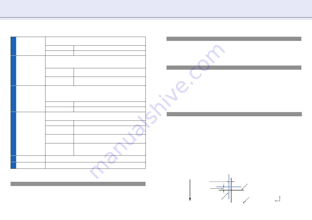
Tool 1-2 Offset ADJ./Tool 1-3 Offset ADJ.

Specify how much Tool 2 or Tool 3 is moved based on the Tool 1.

•Tool 1-2 Offset ADJ.

Adjust the positions of Tool 1 and Tool 2 in the plotter with 2 pen option. Use this setting when there is a difference 

between drawings by the two tools. For adjustment values X and Y, see the fi gure below.

•Tool 1-3 Offset ADJ.

Adjust the positions of Tool 1 and Tool 3 Use this setting when there is a difference between drawings by the two 

tools. For adjustment values X and Y, see the fi gure below.

1.  Correctly set the Cutter plunger or 2 Plotter pens, and turn on the power source. 

2.  Make sure that the plotter is in ready status.

3.  Open the [Tools Setting] screen of the controller.

4.  Click the [Position (use Keyboard)], and then use the keyboard of PC to move the Tool carriage to the position at 

which you want to cut the [+] (test pattern). (For both X and Y directions, move it to 50mm and over inside of the 

plotting area.)

5.  Click [Test Pattern] to cut the test pattern.

6.  Measure the distance between 2 tools through the test pattern plotted.

Cross shape drawn with 
the physical pen 1

The pen's starting 
position

Feed dir

ection of media

Distance adjustment 

value X

Distance 

adjustment 

value Y

Cross shape drawn with

 Tool 2 or 3

X

Y

Summary of Contents for OPS675

Page 1: ...User s Manual MANUAL NO OPS675 UM 152 OPS675 OPS675 OPS675 Cutting Plotter Controller...

Page 2: ...documentation Neither Graphtec nor the supplier gives any explicit or implicit guarantees regarding the infringement of a third party s rights arising from the use of the Software or accompanying manu...

Page 3: ...nual For information on operations from the control panel of the plotter see User s Manual Chapter 2 and Chapter 4 through Chapter 9 in this manual describe the operations and settings that can be don...

Page 4: ...escription that follows this label Reference Used to indicate information useful for operation and additional explanations Used to indicate pages and User s Manuals that contain relevant information U...

Page 5: ...onditions CONDITION 11 Basic Settings 11 Advanced Control of Tool Behavior 13 Cut Test 14 3 Managing Media List 16 4 Tools Setting TOOL 18 5 Setting Area Parameters AREA 21 6 Interface Setting I F 23...

Page 6: ...ork interface 10 Base T 100Base TX USB Interface USB 2 0 Full Speed Serial Interface RS 232C compliant Device Mouse DVD ROM drive 1 Introduction to the Controller Features Reference Cutting Master 3 t...

Page 7: ...one when you start the controller from the Start menu To start the controller from the print menu Start up the controller must be checked This option is in the Options tab of Printing Preferences in t...

Page 8: ...e Controller Starting from the Start Menu 1 From the Start menu select All Programs Graphtec Cutting Plotter Controller for FC8000 and then Cutting Plotter Controller for FC8000 The controller starts...

Page 9: ...s the Edit Media List screen 3 Managing Media List page 16 6 Upload Setting to plotter Overwrites the condition settings tool conditions in the plotter by the settings tool conditions in the controlle...

Page 10: ...Pressing the F1 key on the computer keyboard at each screen displays the help on the setting item 22 Origin Sets the current tool position as an origin point 23 Cross Cut Cuts off the media at the cur...

Page 11: ...and the acceleration when you cut wide media because such media may move during a cutting process and good cut quality may not be obtained When you use a plotter pen set the FORCE to the lowest settin...

Page 12: ...cted 8 Advanced Displays advanced setting items Advanced Control of Tool Behavior page 13 9 OK Saves the set content as the current media name and closes the tool condition setting screen To newly sav...

Page 13: ...ool attached in forward position of the holder is used This setting is used when cutting off the media completely with the backing sheet when cutting them out 2 Distance Adjust Adjust the difference b...

Page 14: ...Cut in User s Manual Some of the buttons are assigned keyboard shortcuts The shortcut keys are as follows Test for force F9 Test for cutter offset Shift F9 Cut Test F8 What is Tangent Emulation The bl...

Page 15: ...increased or decreased by 1 from the original value 3 Test for cutter offset Runs three cutting tests by changing the offset value by 1 The tests are performed with the value that you set and the valu...

Page 16: ...ct it To select multiple conditions click them while pressing the Ctrl or Shift key on the keyboard Media Name page 16 2 Condition No 1 to 8 Assign a Condition No 1 to 8 to the tool condition that is...

Page 17: ...ltiple tool conditions as a single file and load the file The extension of the files that can be imported or exported is GMIE Export 1 Select a condition from the media list and click Export 2 Enter t...

Page 18: ...mm 5 Data Sorting Specify whether to store the data in the buffer memory and sort them before plotting starts What is Data Sorting page 19 Area Off Area sorting is not performed On Area sorting is per...

Page 19: ...stment of the blade direction page 20 2mm Below The initial adjustment of the blade direction is done at 2 mm below the start point of the cutting Outside The initial adjustment of the blade direction...

Page 20: ...e negative values 7 Repeat the procedures 5 to 6 until the difference between tools disappears What is initial adjustment of the blade direction Initial adjustment of the blade direction is an operati...

Page 21: ...5 Close Closes the Area Parameters screen In the main screen page 9 click AREA to open the Area Parameters screen In the Area Parameters screen you set values regarding to the plotting area Reference...

Page 22: ...t Upper Right and Set Lower Left is the plotting area This setting is used when for example you want to plot on a free area on the plotted media To set a plotting area perform the following procedure...

Page 23: ...ate raised or lowered as one right before the instruction is issued When Tool Up is selected the tool is raised and then moved This setting is valid only when the tool is a cutter blade 3 HP GL Origin...

Page 24: ...s available when Registration Marks is checked Mark Auto Scan page 25 3 Mark Distance Specifies the distance between registration marks by using the vertical axis Y and the horizontal axis X Check the...

Page 25: ...using Read Marks regardless the setting in Mark Auto Scan CAUTION To perform a segment area adjustment Adjustment by Using Registration Marks on page 26 the direction where the intermediate registrati...

Page 26: ...stances you set in the X and Y of Mark Distance Registration Marks Setting on page 24 Area segment area adjustment For a long image like one whose length in the feed direction is more than 2 m correct...

Page 27: ...position Specify how much the cross shape which was plotted after scanning should be moved based on the cross shape to be scanned Plotting Registration Mark for Adjustment When Registration Mark is no...

Page 28: ...Normal Set this setting to Slow when heavy or slippery media is used What is Pre Feed page 29 6 Initial Feed Specify whether pre feed should be performed for the length specified by Page Length when t...

Page 29: ...origin point initial feed and cutting area cannot be changed If 1 piece of data causes the buffer to be full partition linking will not be possible Make sure only to send data that is below the buffe...

Page 30: ...e station before turning the power on Enabled The check will be performed 6 Fan Power Set the air volume of the fan that sucks the media Normally select Normal For thin media select Weak 7 Beep For Ke...

Page 31: ...you are logged on as administrator When logging on as the users other than those a message appears and it is unable to return to the media list of default In the main screen page 9 click Option to op...

Page 32: ...to display the error information Click Save in the Error Information screen to save the information in text file format to the computer 7 Condition Information Retrieves and displays the condition inf...

Page 33: ...oller for FC8000 Reboot you computer If the problem still exists uninstall and then re install the controller Uninstalling the Controller on page 33 Setup Manual Registration mark reading has failed C...

Page 34: ...to Scan 24 Mark Distance 24 Mark Scan Mode 26 Mark Type 26 MEDIA 9 Media List Restore to default 32 Media Name 12 Media Sensor 30 Media Setting 28 Mirror 21 Move Step 30 N New 16 O Offset 12 Offset An...

Page 35: ...35 12 Index Information in this document is subject to change without notice OPS675 User s Manual February 28 2013 OPS675 UM 152 2nd GRAPHTEC CORPORATION...

Reviews: