GRAPHTEC OPS675 User Manual Download Page 11

1 1

Performing one of the following tasks opens the corresponding screen for setting tool conditions, 
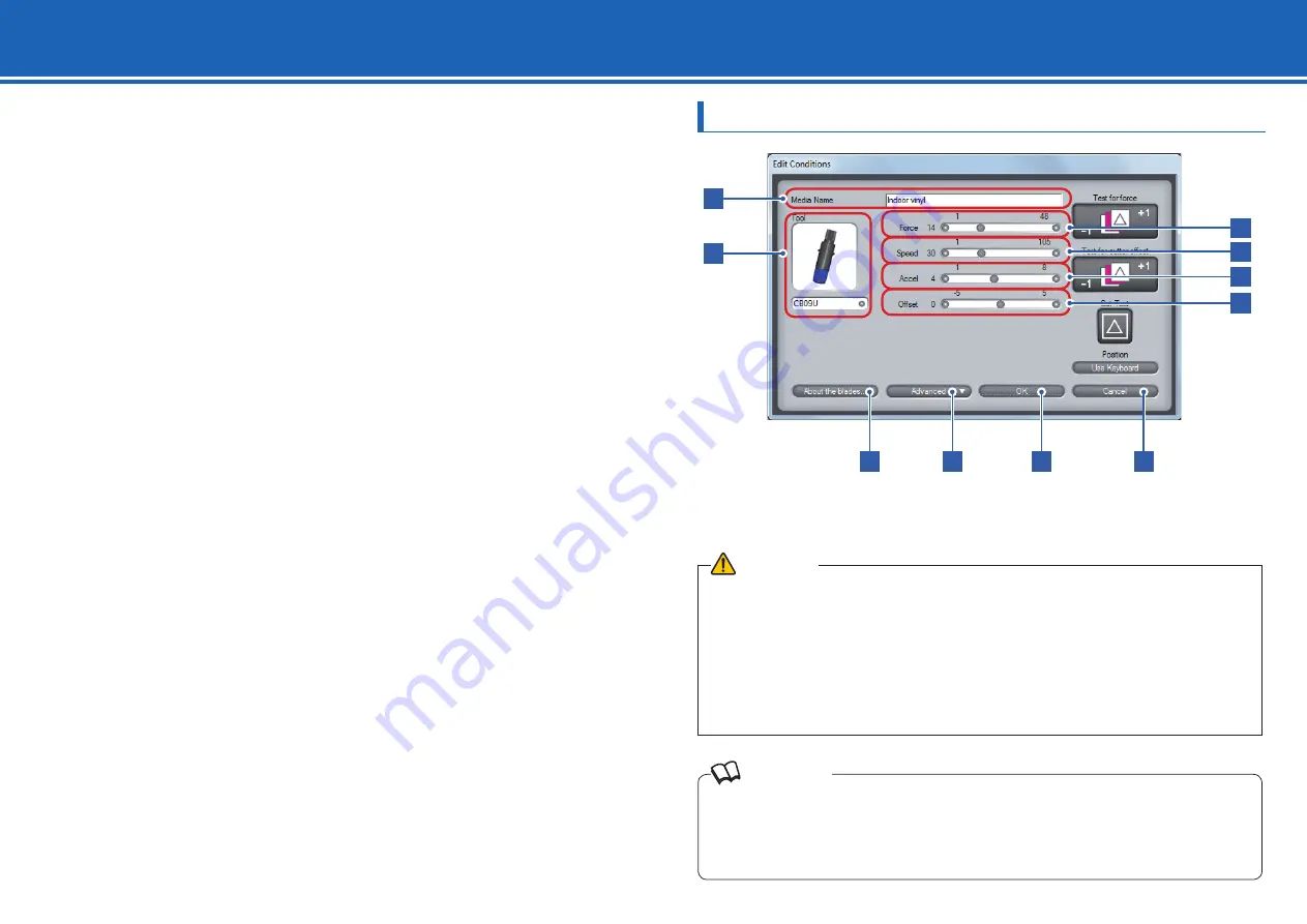
Setting method is the same for all of the screens. In this section, the [Edit Conditions] screen is used 
for explanation.

• In the main screen (

¨

page 9), click [Edit Conditions] to open the [Edit Conditions] screen

• In the [Edit Media List] screen (

¨

page 16), click [Edit] to open the [Edit] screen

• In the [Edit Media List] screen (

¨

page 16), click [New] to open the [New] screen

• In the [Edit Media List] screen (

¨

page 16), click [Copy] to open the [Copy] screen

• In the [Edit Media List] screen (

¨

page 16), click [Load] to open the [Load] screen

In the tool condition setting screens, you can edit a tool condition or create a new one. You can also 
run a cutting test under the condition that you set.

Basic Settings

2.  Setting Tool Conditions [CONDITION]

 Reference

·  Smaller values for the speed and the acceleration require longer cut time, but the quality is stable. Set small 

values for the speed and the acceleration when you cut wide media because such media may move during a 

cutting process and good cut quality may not be obtained.

·  When you use a plotter pen, set the FORCE to the lowest setting to prolong the pen life. Adjust the speed so 

there will be no faint lines. 

 CAUTION

·  Although installing the controller also installs a standard condition setting fi le, optimal settings may differ 

depending on the use environment, the types of media, applications, and other factors. To set values, see 

"Guideline for Settings (for Each Media)" (page 12), "Guideline for Settings (When Plotter Pen is Selected)" 

(page 12), and "Guideline of Offset Setting (for Each Cutter Blade)" (page 12). Be sure to run a cutting test to 

determine the optimal tool condition before performing actual cutting.


¨

"Cut Test" on page 14

·  Clicking [OK] directly after editing the settings overwrites the tool condition under the current media name. To 

create a new tool condition with the settings that you have edited, enter a new name in [Media Name] and 

then click [OK].

Make the basic tool condition settings.
You can set the cutter type, force, speed, acceleration, and offset.

1

2

7

8

9

10

3
4
5
6

Summary of Contents for OPS675

Page 1: ...User s Manual MANUAL NO OPS675 UM 152 OPS675 OPS675 OPS675 Cutting Plotter Controller...

Page 2: ...documentation Neither Graphtec nor the supplier gives any explicit or implicit guarantees regarding the infringement of a third party s rights arising from the use of the Software or accompanying manu...

Page 3: ...nual For information on operations from the control panel of the plotter see User s Manual Chapter 2 and Chapter 4 through Chapter 9 in this manual describe the operations and settings that can be don...

Page 4: ...escription that follows this label Reference Used to indicate information useful for operation and additional explanations Used to indicate pages and User s Manuals that contain relevant information U...

Page 5: ...onditions CONDITION 11 Basic Settings 11 Advanced Control of Tool Behavior 13 Cut Test 14 3 Managing Media List 16 4 Tools Setting TOOL 18 5 Setting Area Parameters AREA 21 6 Interface Setting I F 23...

Page 6: ...ork interface 10 Base T 100Base TX USB Interface USB 2 0 Full Speed Serial Interface RS 232C compliant Device Mouse DVD ROM drive 1 Introduction to the Controller Features Reference Cutting Master 3 t...

Page 7: ...one when you start the controller from the Start menu To start the controller from the print menu Start up the controller must be checked This option is in the Options tab of Printing Preferences in t...

Page 8: ...e Controller Starting from the Start Menu 1 From the Start menu select All Programs Graphtec Cutting Plotter Controller for FC8000 and then Cutting Plotter Controller for FC8000 The controller starts...

Page 9: ...s the Edit Media List screen 3 Managing Media List page 16 6 Upload Setting to plotter Overwrites the condition settings tool conditions in the plotter by the settings tool conditions in the controlle...

Page 10: ...Pressing the F1 key on the computer keyboard at each screen displays the help on the setting item 22 Origin Sets the current tool position as an origin point 23 Cross Cut Cuts off the media at the cur...

Page 11: ...and the acceleration when you cut wide media because such media may move during a cutting process and good cut quality may not be obtained When you use a plotter pen set the FORCE to the lowest settin...

Page 12: ...cted 8 Advanced Displays advanced setting items Advanced Control of Tool Behavior page 13 9 OK Saves the set content as the current media name and closes the tool condition setting screen To newly sav...

Page 13: ...ool attached in forward position of the holder is used This setting is used when cutting off the media completely with the backing sheet when cutting them out 2 Distance Adjust Adjust the difference b...

Page 14: ...Cut in User s Manual Some of the buttons are assigned keyboard shortcuts The shortcut keys are as follows Test for force F9 Test for cutter offset Shift F9 Cut Test F8 What is Tangent Emulation The bl...

Page 15: ...increased or decreased by 1 from the original value 3 Test for cutter offset Runs three cutting tests by changing the offset value by 1 The tests are performed with the value that you set and the valu...

Page 16: ...ct it To select multiple conditions click them while pressing the Ctrl or Shift key on the keyboard Media Name page 16 2 Condition No 1 to 8 Assign a Condition No 1 to 8 to the tool condition that is...

Page 17: ...ltiple tool conditions as a single file and load the file The extension of the files that can be imported or exported is GMIE Export 1 Select a condition from the media list and click Export 2 Enter t...

Page 18: ...mm 5 Data Sorting Specify whether to store the data in the buffer memory and sort them before plotting starts What is Data Sorting page 19 Area Off Area sorting is not performed On Area sorting is per...

Page 19: ...stment of the blade direction page 20 2mm Below The initial adjustment of the blade direction is done at 2 mm below the start point of the cutting Outside The initial adjustment of the blade direction...

Page 20: ...e negative values 7 Repeat the procedures 5 to 6 until the difference between tools disappears What is initial adjustment of the blade direction Initial adjustment of the blade direction is an operati...

Page 21: ...5 Close Closes the Area Parameters screen In the main screen page 9 click AREA to open the Area Parameters screen In the Area Parameters screen you set values regarding to the plotting area Reference...

Page 22: ...t Upper Right and Set Lower Left is the plotting area This setting is used when for example you want to plot on a free area on the plotted media To set a plotting area perform the following procedure...

Page 23: ...ate raised or lowered as one right before the instruction is issued When Tool Up is selected the tool is raised and then moved This setting is valid only when the tool is a cutter blade 3 HP GL Origin...

Page 24: ...s available when Registration Marks is checked Mark Auto Scan page 25 3 Mark Distance Specifies the distance between registration marks by using the vertical axis Y and the horizontal axis X Check the...

Page 25: ...using Read Marks regardless the setting in Mark Auto Scan CAUTION To perform a segment area adjustment Adjustment by Using Registration Marks on page 26 the direction where the intermediate registrati...

Page 26: ...stances you set in the X and Y of Mark Distance Registration Marks Setting on page 24 Area segment area adjustment For a long image like one whose length in the feed direction is more than 2 m correct...

Page 27: ...position Specify how much the cross shape which was plotted after scanning should be moved based on the cross shape to be scanned Plotting Registration Mark for Adjustment When Registration Mark is no...

Page 28: ...Normal Set this setting to Slow when heavy or slippery media is used What is Pre Feed page 29 6 Initial Feed Specify whether pre feed should be performed for the length specified by Page Length when t...

Page 29: ...origin point initial feed and cutting area cannot be changed If 1 piece of data causes the buffer to be full partition linking will not be possible Make sure only to send data that is below the buffe...

Page 30: ...e station before turning the power on Enabled The check will be performed 6 Fan Power Set the air volume of the fan that sucks the media Normally select Normal For thin media select Weak 7 Beep For Ke...

Page 31: ...you are logged on as administrator When logging on as the users other than those a message appears and it is unable to return to the media list of default In the main screen page 9 click Option to op...

Page 32: ...to display the error information Click Save in the Error Information screen to save the information in text file format to the computer 7 Condition Information Retrieves and displays the condition inf...

Page 33: ...oller for FC8000 Reboot you computer If the problem still exists uninstall and then re install the controller Uninstalling the Controller on page 33 Setup Manual Registration mark reading has failed C...

Page 34: ...to Scan 24 Mark Distance 24 Mark Scan Mode 26 Mark Type 26 MEDIA 9 Media List Restore to default 32 Media Name 12 Media Sensor 30 Media Setting 28 Mirror 21 Move Step 30 N New 16 O Offset 12 Offset An...

Page 35: ...35 12 Index Information in this document is subject to change without notice OPS675 User s Manual February 28 2013 OPS675 UM 152 2nd GRAPHTEC CORPORATION...

Reviews: